LIGHTING (EXT) HEADLIGHT ECU INSTALLATION
CAUTION / NOTICE / HINT
- HINT:
- ·
Use the same procedure for both the LH and RH sides.
·The procedure described below is for the LH side.
PROCEDURE

 85967D
1.INSTALL LIGHT CONTROL LED ECU
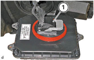
Connect the connector (1).
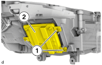
Set the light control LED ECU (2) in the headlight assembly.
Install the T20 screws (1).
- Torque:
- 1.5 N*m (15 kgf*cm, 13 in.*lbf)
81150
2.INSTALL HEADLIGHT ASSEMBLY
3. ENCODE/PROGRAM CONTROL UNIT(S)
- NOTICE:
- ·
Use the most recent software version to prevent faults during programming/encoding.
·The battery voltage must not drop below 13.0 V during programming.
·Use only recommended chargers for a low-voltage vehicle electrical system.
·Do not exceed the maximum charging voltage of 14.8 V when charging the battery.
·When there is communication abnormality in the middle of work, control unit might be damaged.
·It may be necessary to perform the Action Plan several times.
Connect the battery charger to the vehicle.
Connect the diagnosis system with the vehicle.
Determine the action plan.
Service plan / Programming plan / Action plan / Calculate action plan
Accept and fully process the measures plan.
Service plan / Programming plan / Action plan / Perform action plan
Wait until programming/encoding has been completed.
- NOTICE:
-
When there is communication abnormality in the middle of work, control unit might be damaged.
Carry out vehicle test.
Vehicle management / Troubleshooting / Fault memory / Calculate test plan
Delete the fault memory.
Vehicle management / Troubleshooting / Fault memory / Delete fault memory
Disconnect the diagnosis system from the vehicle.
Disconnect the battery charger from the vehicle.