REAR SUSPENSION REAR UPPER ARM INSTALLATION
CAUTION / NOTICE / HINT
- HINT:
- ·
Use the same procedure for the RH side and LH side.
·The following procedure is for the LH side.
PROCEDURE

 48790F
1.INSTALL REAR NO. 2 UPPER CONTROL ARM ASSEMBLY
- CAUTION:
- ·
The rear suspension member sub-assembly is a very heavy component. Make sure that it is supported securely.
·If the rear suspension member sub-assembly is not securely supported, it may drop, resulting in serious injury.
- NOTICE:
-
Use attachments and wooden blocks to keep the rear suspension member sub-assembly level.
- HINT:
-
Tighten the bolt connection in the normal position.
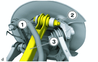
Position the rear No. 2 upper control arm assembly (3).
Replace the 18 mm bolt (1) and the 18 mm nut (2).
Position 18 mm bolt (1).
Tighten 18 mm nut (2).
- Torque:
- 100 N*m (1020 kgf*cm, 74 ft.*lbf)
Using SST, tighten the nut (2) an additional 90°.
- SST
- 09900-WA010
- HINT:
- ·
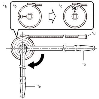 2.99,1.271 3.156,1.188 false 2.906,2.094 2.906,1.76 false 0.875,3 1.208,3 false 0.104,0.125 0.417,0.281 0.313,0.156 10 false *a 0.448,0.125 0.76,0.281 0.313,0.156 10 false *b 2.042,0.125 2.354,0.281 0.313,0.156 10 false *c 3.188,1.073 3.427,1.271 0.24,0.198 10 false *d 2.854,2.146 3.167,2.302 0.313,0.156 10 false *b 1.302,2.927 1.615,3.083 0.313,0.156 10 false *c
*a Example *b Before Tightening *c After Tightening *d Magnetic Portion
·The magnetic portion is used to secure the gauge to the vehicle.
·After first adjusting the needle of the gauge to 0°, tighten to the specified angle.
·Perform the work procedure carefully so that the gauge, etc. does not become tilted.
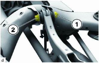
Replace the 18 mm nut (1) and 16 mm bolt (2).
Position 16 mm bolt (2).
Tighten 18 mm nut (1).
- Torque:
- 100 N*m (1020 kgf*cm, 74 ft.*lbf)
Using SST, tighten the nut (1) an additional 90°.
- SST
- 09900-WA010
- HINT:
- ·
2.99,1.271 3.156,1.188 false 2.906,2.094 2.906,1.76 false 0.875,3 1.208,3 false 0.104,0.125 0.417,0.281 0.313,0.156 10 false *a 0.448,0.125 0.76,0.281 0.313,0.156 10 false *b 2.042,0.125 2.354,0.281 0.313,0.156 10 false *c 3.188,1.073 3.427,1.271 0.24,0.198 10 false *d 2.854,2.146 3.167,2.302 0.313,0.156 10 false *b 1.302,2.927 1.615,3.083 0.313,0.156 10 false *c
*a Example *b Before Tightening *c After Tightening *d Magnetic Portion
·The magnetic portion is used to secure the gauge to the vehicle.
·After first adjusting the needle of the gauge to 0°, tighten to the specified angle.
·Perform the work procedure carefully so that the gauge, etc. does not become tilted.
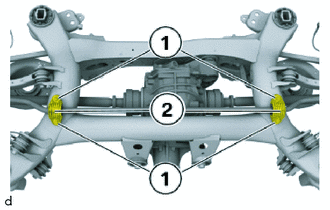
Position rear No. 1 stabilizer bar bracket (2) on the rear stabilizer bar.
Replace E12 bolts (1).
Tighten the E12 bolts (1).
- Torque:
- 21.4 N*m (218 kgf*cm, 16 ft.*lbf)
48790
2.INSTALL REAR UPPER CONTROL ARM ASSEMBLY
- CAUTION:
- ·
The rear suspension member sub-assembly is a very heavy component. Make sure that it is supported securely.
·If the rear suspension member sub-assembly is not securely supported, it may drop, resulting in serious injury.
- NOTICE:
-
Use attachments and wooden blocks to keep the rear suspension member sub-assembly level.
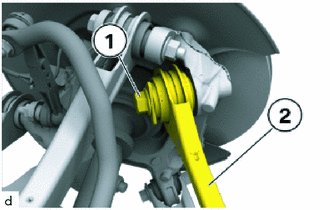
Position the rear upper control arm assembly (2).
Replace the bolt (1).
Tighten down bolt (1).
- Torque:
- 165 N*m (1683 kgf*cm, 122 ft.*lbf)
Using SST, tighten the bolt (1) an additional 90°.
- SST
- 09900-WA010
- HINT:
- ·
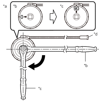 2.99,1.271 3.156,1.188 false 2.906,2.094 2.906,1.76 false 0.875,3 1.208,3 false 0.104,0.125 0.417,0.281 0.313,0.156 10 false *a 0.448,0.125 0.76,0.281 0.313,0.156 10 false *b 2.042,0.125 2.354,0.281 0.313,0.156 10 false *c 3.188,1.073 3.427,1.271 0.24,0.198 10 false *d 2.854,2.146 3.167,2.302 0.313,0.156 10 false *b 1.302,2.927 1.615,3.083 0.313,0.156 10 false *c
*a Example *b Before Tightening *c After Tightening *d Magnetic Portion
·The magnetic portion is used to secure the gauge to the vehicle.
·After first adjusting the needle of the gauge to 0°, tighten to the specified angle.
·Perform the work procedure carefully so that the gauge, etc. does not become tilted.
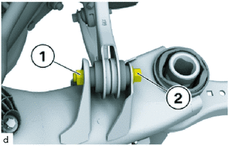
Replace the 16 mm bolt (2) and the 18 mm nut (1).
Tighten 18 mm nut (1).
- Torque:
- 100 N*m (1020 kgf*cm, 74 ft.*lbf)
Using a digital angle torque wrench, tighten the 18 mm nut (1) an additional 90°.
- HINT:
- ·
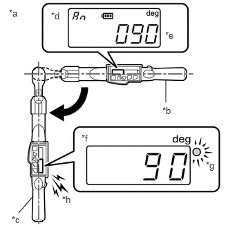 2.5,1.542 2.5,1.208 false 0.49,2.969 0.281,3.208 false 0.135,0.115 0.448,0.271 0.313,0.156 10 false *a 2.448,1.583 2.76,1.74 0.313,0.156 10 false *b 0.177,3.229 0.49,3.385 0.313,0.156 10 false *c 0.771,0.156 1.083,0.313 0.313,0.156 10 false *d 2.49,0.448 2.802,0.604 0.313,0.156 10 false *e 1.229,2 1.542,2.156 0.313,0.156 10 false *f 3.104,2.406 3.417,2.563 0.313,0.156 10 false *g 0.938,2.927 1.25,3.083 0.313,0.156 10 false *h
*a Example *b Before Tightening *c After Tightening *d Set Angle Display *e Setting the Specified Angle *f Tightening Angle Display *g LED Notification *h Buzzer Notification
·When using the digital angle torque wrench, set the wrench to the specified tightening angle before use.
·When using the digital angle torque wrench, check the tightening angle display while performing the work.
·When tightening reaches the set angle, the buzzer will sound and a blue LED will illuminate.
51206A
3.INSTALL REAR SUSPENSION MEMBER SUB-ASSEMBLY