B58 LUBRICATION OIL PUMP INSTALLATION
PROCEDURE

 15100
1.INSTALL OIL PUMP ASSEMBLY
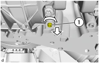
Work oil pump set pins (1) out of the crankcase in the direction of the arrow and remove.
Replace the oil pump set pins (1).
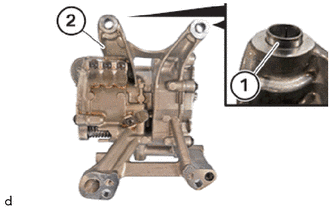
Insert oil pump set pins (1) in to the oil pump assembly (2) and install.
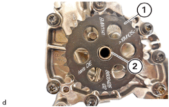
Position oil pump drive shaft gear (1) on the oil pump assembly (2).
- NOTICE:
-
The labelling on the oil pump drive shaft gear (1) must face away from the oil pump assembly (2).
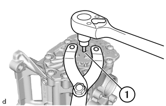
Replace the T45 bolt (1).
Insert T45 bolt (1) and fit.
- HINT:
-
The thread is a left-hand thread.
Hold oil pump drive shaft gear with SST and tighten T45 bolt (1).
- SST
- 09960-10010 (09962-01000, 09963-00700)
- Torque:
- 5.0 N*m (51 kgf*cm, 44 in.*lbf)
- HINT:
-
Conduct the following operation with the assistance of a second person.
Using SST, tighten the T45 bolt (1) an additional 90°.
- SST
- 09900-WA010
- HINT:
-
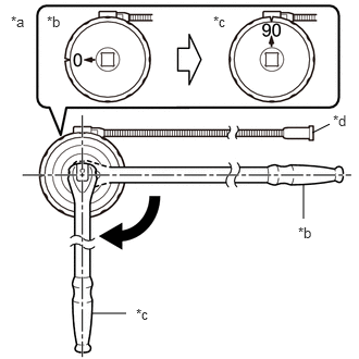 2.99,1.271 3.156,1.188 false 2.906,2.094 2.906,1.76 false 0.875,3 1.208,3 false 0.104,0.125 0.417,0.281 0.313,0.156 10 false *a 0.448,0.125 0.76,0.281 0.313,0.156 10 false *b 2.042,0.125 2.354,0.281 0.313,0.156 10 false *c 3.188,1.073 3.427,1.271 0.24,0.198 10 false *d 2.854,2.146 3.167,2.302 0.313,0.156 10 false *b 1.302,2.927 1.615,3.083 0.313,0.156 10 false *c
*a Example *b Before Tightening *c After Tightening *d Magnetic Portion
- ·
The magnetic portion is used to secure the gauge to the vehicle.
·After first adjusting the needle of the gauge to 0°, tighten to the specified angle.
·Perform the work procedure carefully so that the gauge, etc. does not become tilted.
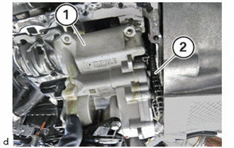
Feed the oil pump assembly (1) into the oil pump drive chain sub-assembly (2) and position it.
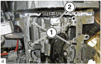
Replace E10 bolts (1).
Tighten the E10 bolts (1).
- Torque:
- 15 N*m (153 kgf*cm, 11 ft.*lbf)
Using SST, tighten the E10 bolts (1) an additional 45°.
- SST
- 09900-WA010
- HINT:
-
2.99,1.271 3.156,1.188 false 2.906,2.094 2.906,1.76 false 0.875,3 1.208,3 false 0.104,0.125 0.417,0.281 0.313,0.156 10 false *a 0.448,0.125 0.76,0.281 0.313,0.156 10 false *b 2.042,0.125 2.354,0.281 0.313,0.156 10 false *c 3.188,1.073 3.427,1.271 0.24,0.198 10 false *d 2.854,2.146 3.167,2.302 0.313,0.156 10 false *b 1.302,2.927 1.615,3.083 0.313,0.156 10 false *c
*a Example *b Before Tightening *c After Tightening *d Magnetic Portion
- ·
The magnetic portion is used to secure the gauge to the vehicle.
·After first adjusting the needle of the gauge to 0°, tighten to the specified angle.
·Perform the work procedure carefully so that the gauge, etc. does not become tilted.
12101
2.INSTALL OIL PAN SUB-ASSEMBLY