SEAT LUMBAR SUPPORT ADJUSTER ASSEMBLY REMOVAL
CAUTION / NOTICE / HINT
- CAUTION:
- ·
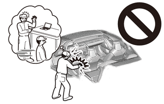
Airbag unit.
Danger! Life-threatening injuries!
-Before performing any work on the airbag, always disconnect the battery earth lead from the battery.
-Airbag unit may only be set down with the cushion (airbag itself) facing upwards.
-All work on pyrotechnic parts may be carried out by technically experienced and appropriately trained personnel only.
-Replace any damaged part or ones that have been dropped.
-For additional information see:
Click hereVehicle Interior>SUPPLEMENTAL RESTRAINT SYSTEMS>AIRBAG SYSTEM>PRECAUTION
·Wear protective gloves. Sharp areas on the parts may injure your hands.
- NOTICE:
- ·
Before performing work on electronic components, disconnect the cable from the negative (-) battery terminal to prevent damage to the electrical system or components.
·When disconnecting the cable, turn the START-STOP button (engine switch) and headlight switch off and loosen the cable nut completely. Perform these operations without twisting or prying on the cable. Then disconnect the cable.
·Clock settings, radio settings, audio system memory, DTCs and other data will be cleared when the cable is disconnected from the negative (-) battery terminal. Write down any necessary data before disconnecting the cable.
- HINT:
- ·
Use the same procedure for RHD and LHD vehicles.
·The procedure listed below is for LHD vehicles.
·Use the same procedure for the driver side and front passenger side.
·The procedure listed below is for the driver side.
PROCEDURE

 1.REMOVE SEPARATE TYPE FRONT SEATBACK COVER WITH PAD (for Manual Seat)
2.REMOVE SEPARATE TYPE FRONT SEATBACK COVER WITH PAD (for Power Seat)
72760D
3.REMOVE LUMBAR SUPPORT ADJUSTER ASSEMBLY
w/ Back Side Support Adjuster:
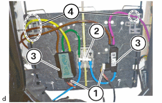
Disconnect the connectors (1).
Disconnect the pneumatic tubes connector (2).
Detach the pneumatic tubes from the holders in the marked area (4).
Remove the valve units (3) from the spring wire.
w/o Back Side Support Adjuster:
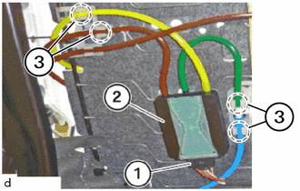
Disconnect the connector (1).
Detach the pneumatic tubes from the holder in the marked area (3).
Remove the valve unit (2) from the spring wire.
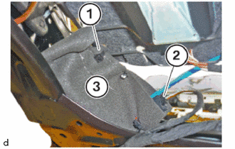
Remove the tie band (1).
Disconnect the connector (2).
Remove the pump (3).
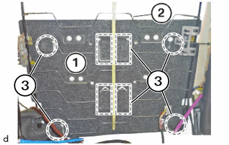
Remove the lumbar support adjuster assembly (1) in the marked areas (3) from the spring wire (2).