B48 FUEL FUEL INJECTOR REMOVAL
CAUTION / NOTICE / HINT
- CAUTION:
- ·
Working on 12 V vehicle electrical system.
Risk of short circuits! Risk of fire!
-Detach battery earth lead from battery.
-For an auxiliary battery: Disconnect battery earth lead of auxiliary battery.
- NOTICE:
- ·
Damage to battery terminal, the safety battery terminal or the intelligent battery sensor (IBS).
·Damaged battery terminals can lead to malfunctions or vehicle electrical system faults.
-Pull off battery terminal from battery pole by carefully moving to and fro. Do not pry off using a tool.
PROCEDURE

 23801P
1.REMOVE NO. 1 FUEL PIPE SUB-ASSEMBLY
23250
2.REMOVE FUEL INJECTOR ASSEMBLY
- NOTICE:
- ·
Damage to injectors.
·Excessive force may damage the injector and this means having to renew the injector.
-Twist the injectors with a maximum torsional movement of 13 Nm.
- ·
Damage to the injector tips and Teflon ring.
·Improper handling of the injector tips and Teflon ring can lead to malfunctioning of the injector.
-Avoid mechanical contact with injector tip.
-When exchanging Teflon ring, hands and work surface must be clean and free of oil. Do not use any lubricating agents.
-Do not use fingernails to slide Teflon ring on.
- ·
Contaminant or foreign body.
·Contamination can result in malfunctions, operating failure or leaks.
-Adhere to the utmost cleanliness.
-Protect components from contamination e.g. by covering.
-Close off line connections with seal plugs.
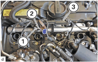
Unfasten nut (1).
Feed out ground cable (2) and set it aside.
Feed out cable channel (3) and set it aside.
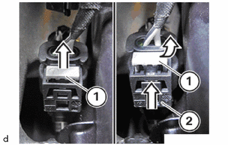
Unlock lock (1) in direction of arrow from the top.
Press lock (1) together and release.
Pull off the connector (2) from the injectors.
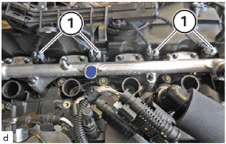
Unlock and disconnect all connectors (1) of the injectors.
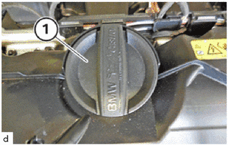
Unscrew the sealing cap (1) from the oil filler neck.
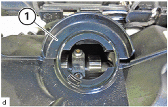
Release drip protection (1) from the cylinder head cover.
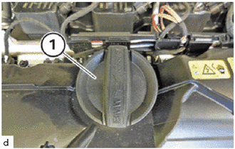
Screw the sealing cap (1) onto the oil filler neck.
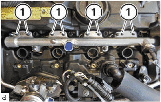
Unscrew and remove the E6 bolts (1).
- NOTICE:
-
Do not reuse the bolts (1).
Catch and dispose of escaping fuel with suitable materials.
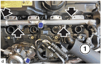
Unscrew and remove E8 bolts (arrows).
- NOTICE:
-
Do not reuse the screws.
Unlock plug connection (1) and disconnect.
Remove rail in upward direction.
- HINT:
-
The injectors remain in the cylinder head.
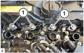
Remove the gaskets (1).
- HINT:
-
The seals (1) are required during first assembly within the plant only and will not be installed again.
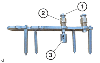
In the event that the specified value for the tensile force is exceeded: Replace injectors.
- NOTICE:
- ·
Damage to injectors.
·Excessive force may damage the injector and this means having to renew the injector.
-Twist the injectors with a maximum torsional movement of 13 Nm.
Use the special tool 2 358 417 to remove the injectors.
- SST
- 09200-WA520 09200-WA680
Special tool 2 358 417 is used to ensure that the tensile force is not exceeded.
- SST
- 09200-WA520 09200-WA680
The special tool 2 358 417 consists of:
- SST
- 09200-WA520 09200-WA680
(1) Threaded sleeves
(2) Pull-out thread (left-hand thread)
(3) Fixture for the injector
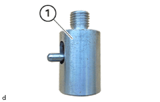
Unscrew the fixture for the injectors (1) from the special tool 2 358 417 .
- SST
- 09200-WA520 09200-WA680
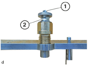
Press the lock (1) in and remove threaded sleeve (2) from the special tool 2 358 417 .
- SST
- 09200-WA520 09200-WA680
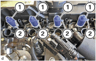
Install all fixtures (1) for the injectors.
- HINT:
-
The fixture (1) is not locked if the lever (2) is on the top.
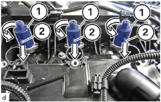
Turn the fixtures (1) by 90° and lock the levers (2) downward.
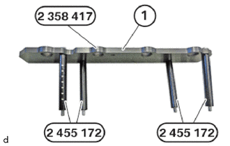
Prepare the panel (1) from the special tool 2 358 417 with the spacer sleeves 2 455 172 .
- SST
- 09200-WA520 09200-WA680
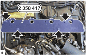
Attach special tool 2 358 417 to cylinder head.
- SST
- 09200-WA520 09200-WA680
- NOTICE:
- ·
Damage to injectors.
·Excessive force may damage the injector and this means having to renew the injector.
-Do not use the puller plate as a support.
Hand-tighten the bolts (arrows).
- HINT:
-
The extraction thread is a left-hand thread.
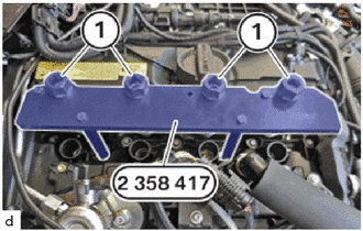
Screw in pull-out thread (1) on the special tool 2 358 417 fully.
- SST
- 09200-WA520 09200-WA680
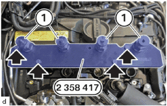
Insert the threaded sleeves (1) again and screw threaded sleeves completely onto the fixtures for the injectors.
Tighten the screws (arrows) on the special tool 2 358 417 .
- SST
- 09200-WA520 09200-WA680
- Torque:
- 5.0 N*m (51 kgf*cm, 44 in.*lbf)
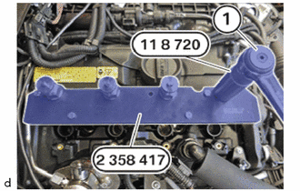
Adjust the torque wrench to 13 Nm, clockwise rotation.
Turn torque wrench (1) in clockwise direction with 24 mm deep socket wrench until the injector is pulled out.
- SST
- 09200-WA180
- HINT:
-
If the torque wrench makes a cracking noise when the injector is pulled out, the injector must be renewed.
Disassemble all injectors individually.
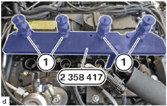
Before removing the special tool 2 358 417 with the injectors, check if all the injectors were completely pulled out of the cylinder head.
- SST
- 09200-WA520 09200-WA680
- HINT:
-
The threads of the pull-out thread must be completely visible.
Loosen screws on special tool 2 358 417 .
- SST
- 09200-WA520 09200-WA680
Carefully remove the special tool 2 358 417 with the injectors (1) vertically straight up from the cylinder head.
- SST
- 09200-WA520 09200-WA680
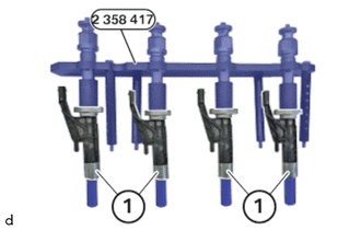
Place the combination of the special tool 2 358 417 and the injectors (1) flat on a clean table.
- SST
- 09200-WA520 09200-WA680
- NOTICE:
-
The description is for one component only. The procedure is identical for all further components.
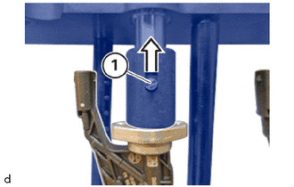
Unlock the fixture lock (1) from the top.
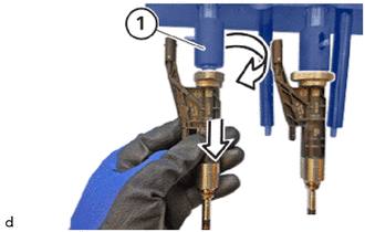
Turn the unlocked fixture (1) by 90°.
Release and remove the injector downwards.