RM3650E
_51
Engine / Hybrid System
_080178
B48 ENGINE MECHANICAL
_0388863
ROCKER ARM
A
B48 ENGINE MECHANICAL ROCKER ARM INSTALLATION
PROCEDURE

 13801
1.INSTALL NO.1 VALVE ROCKER ARM SUB-ASSEMBLY
a.
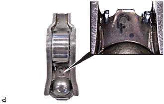
Observe the classification of the No. 1 valve rocker arm sub-assembly.
i.
The classification from 1 to 5 is printed on the respective roller cam follower.
| Classification | Idle speed |
|---|---|
| 1 | Repair case - slow engine speed when idling |
| 2 | Installed as standard/initial installation |
| 3 | Installed as standard/initial installation |
| 4 | Installed as standard/initial installation |
| 5 | Repair case - high engine speed when idling |
b.
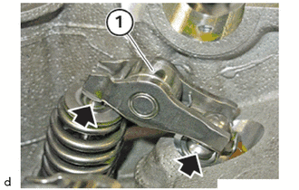
Install the No. 1 valve rocker arm sub-assembly (1) on the intake side.
c.
Make sure the No. 1 valve rocker arm sub-assemblies are correctly positioned on the valve lash adjuster assemblies (arrows) and on the intake valves.
d.
Install the No. 1 valve rocker arm sub-assembly (1) on the exhaust side.
e.
Make sure the No. 1 valve rocker arm sub-assemblies are correctly positioned on the valve lash adjuster assemblies (arrows) and on the exhaust valves.
2.INSTALL CAMSHAFT