B48 ENGINE MECHANICAL CAMSHAFT INSTALLATION
PROCEDURE

 13502B
1.INSTALL EXHAUST CAMSHAFT SUB-ASSEMBLY
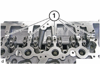
Coat all bearing positions (1) with fresh engine oil.
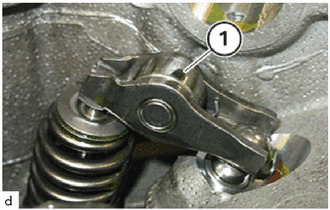
Ensure the correct fit of the No. 1 valve rocker arm sub-assembly (1) before mounting the exhaust camshaft sub-assembly.
Coat the exhaust camshaft sub-assembly and the exhaust camshaft bearing cap with fresh engine oil.
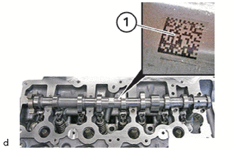
Insert exhaust camshaft sub-assembly in the cylinder head sub-assembly, such that the mark (1) points upwards.
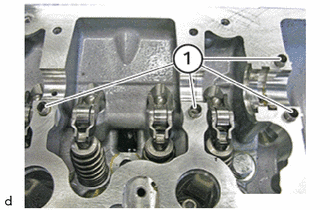
Check the ring pins (1) for correct fit and damage and replace as needed.
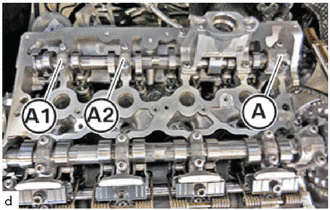
Position all exhaust camshaft bearing caps correctly on the cylinder head sub-assembly.
The exhaust camshaft bearing caps are legibly labelled from the intake side and marked with (A1), (A2) and (A).
The exhaust camshaft bearing cap (A) is a thrust bearing.
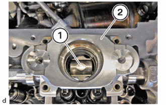
Coat both bearing positions on the exhaust camshaft bearing cap with fresh engine oil.
Guide in and position the exhaust camshaft bearing cap (2) with the roller tappet (1).
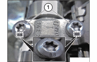
Check the tensile strength of the screws for the bearing caps. The figure shows the screw with the tensile strength of 8,8.
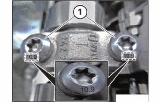
Check the tensile strength of the screws for the bearing caps. The figure shows the screw with the tensile strength of 10,9.
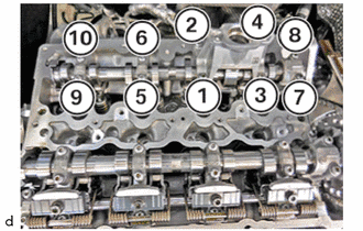
Press down the exhaust camshaft bearing caps and hand-tighten the T30 bolts incrementally in the sequence (1) to (10).
Attach the screws in the sequence (1) to (10) in half turns to the unit.
Adhere to the jointing torque.
Tighten all T30 bolts of the exhaust camshaft bearing caps in sequence (1) to (10).
- Torque:
- Tensile strength of screw 8.8 : 9.6 N*m (98 kgf*cm, 85 in.*lbf)
- Tensile strength ofb screw 10.9 : 11.8 N*m (120 kgf*cm, 9 ft.*lbf)
13501A
2.INSTALL INTAKE CAMSHAFT SUB-ASSEMBLY
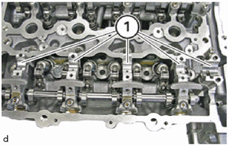
Coat all bearing positions (1) with fresh engine oil.
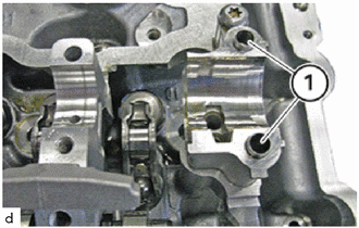
Check the ring pins (1) for correct fit and damage and replace as needed.
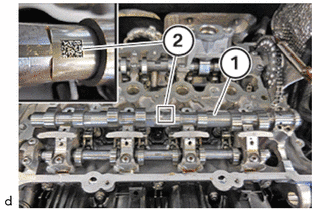
Insert the intake camshaft sub-assembly (1) into the cylinder head sub-assembly so that the mark (2) points up.
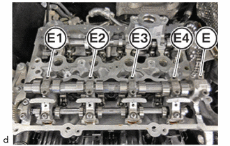
Position all camshaft bearing caps correctly on the cylinder head sub-assembly.
The camshaft bearing caps are legible from the intake side and they are marked with (E1), (E2), (E3), (E4) and (E).
The camshaft bearing cap (E) is a thrust bearing.
Check the tensile strength of the screws for the bearing caps. The figure shows the screw with the tensile strength of 8.8.
Check the tensile strength of the screws for the bearing caps. The figure shows the screw with the tensile strength of 10.9.
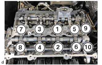
Press down the camshaft bearing caps and hand-tighten the T30 bolts incrementally in the sequence (1) to (10).
Attach the screws in the sequence (1) to (10) in half turns tothe unit.
Adhere to the jointing torque.
Tighten all T30 bolts in sequence from (1) to (10).
- Torque:
- Tensile strength ofscrew 8.8 : 9.6 N*m (98 kgf*cm, 85 in.*lbf)
- Tensile strength ofscrew 10.9 : 11.8 N*m (120 kgf*cm, 9 ft.*lbf)
13800
3.INSPECT INTERMEDIATE LEVER
13800
4.INSTALL INTERMEDIATE LEVER
13908A
5.INSTALL GATE
6.INSTALL TORSION SPRING
- CAUTION:
- ·
Spring preload.
Danger of injury!
-The use of the specified special tool (tool) is mandatory.
-The described operation must be carried out properly.
- HINT:
-
Wear safety goggles.
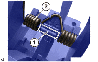
Insert the torsion spring (2) in the clamping lever of the special tool 2 359 088.
- SST
- 09200-WA410
Make sure that the torsion spring (2) is correctly positioned in the marked area (1) of the special tool 2 359 088.
- SST
- 09200-WA410
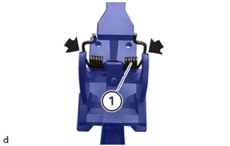
Ensure that the torsion spring (1) lies correctly in the lateral guides (arrows) of the special tool 2 359 088.
- SST
- 09200-WA410
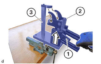
Carefully close the clamping lever (2) of the special tool 2 359 088 in the fixture (3) until the retaining hook (1) audibly engages.
- SST
- 09200-WA410
The torsion spring is tensioned.
Carefully take the clamping lever (2) of the special tool 2 359 088 with the stretched torsion spring out of the fixture (3) of the special tool 2 359 088 in the direction of arrow.
- SST
- 09200-WA410
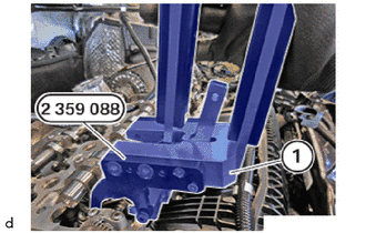
Guide in and position clamping lever (1) of the special tool 2 359 088 on the cylinder head sub-assembly with the clamped torsion spring.
- SST
- 09200-WA410
Ensure that the clamping lever (1) of the special tool lies flat in the area of the cylinder head sub-assembly.
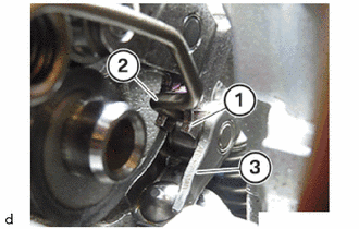
Ensure that the torsion spring (2) in the intermediate lever (1) is positioned correctly.
Check the No. 1 valve rocker arm sub-assembly (3) for correct mounting orientation.
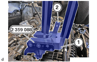
Carefully unlock the retaining hook (2) on the clamping lever (1) of the special tool 2 359 088.
- SST
- 09200-WA410
The torsion spring tension is relieved.
Guide out and remove the clamping lever (1) of the special tool 2 359 088.
- SST
- 09200-WA410
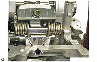
Check for correct mounting orientation of the torsion spring (arrow) at the cylinder head sub-assembly.
Repeat the operations for the remaining torsion spring.
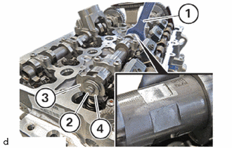
Guide in the camshaft sensor wheel (3) and install.
Make sure that camshaft sensor wheel (3) is positioned correctly on guide pin (4).
Secure the intake camshaft sub-assembly with a conventional open-end spanner (1).
Tighten down bolt (2).
- Torque:
- 8.0 N*m (82 kgf*cm, 71 in.*lbf)
7.ADJUST CAMSHAFT
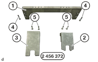
Have the set of special tools 2 456 372 ready.
- SST
- 09200-WA700
| Number | Description |
|---|---|
| 1 | Basic carrier |
| 2 | 0.7° setting gauge to adjust the intake camshaft sub-assembly |
| 3 | 0.5° setting gauge to adjust the exhaust camshaft sub-assembly |
| 4 | Basic carrier bolts on cylinder head |
| 5 | Bolt gauge on basic carrier |
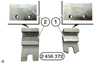
Use the setting gauge 0.7 ° (1) from the set of special tools 2 456 372 to adjust the intake camshaft sub-assembly.
- SST
- 09200-WA700
Use the setting gauge 0.5 ° (2) from the set of special tools 2 456 372 to adjust the exhaust camshaft sub-assembly.
- SST
- 09200-WA700
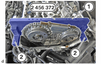
Position the basic carrier (1) from the set of special tools 2 456 372 on the cylinder head sub-assembly.
- SST
- 09200-WA700
Tighten the bolts (2) from the set of special tools 2 456 372.
- SST
- 09200-WA700
- Torque:
- 8.0 N*m (82 kgf*cm, 71 in.*lbf)
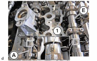
Turn the intake camshaft sub-assembly (E) and the exhaust camshaft sub-assembly (A) until the marks (1) can be read from the top.
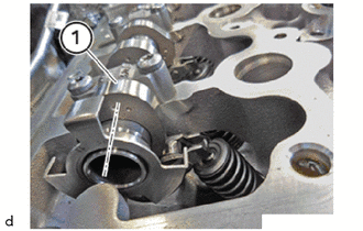
Ensure that the cam (1) on the exhaust camshaft sub-assembly on cylinder 1 points to the inside right at a slight angle.
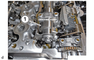
Ensure that the cam (1) on the intake camshaft sub-assembly on cylinder 1 points to the inside left at an angle.
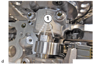
Ensure that the flattened areas (1) on the intake camshaft sub-assembly and the exhaust camshaft sub-assembly point upwards.
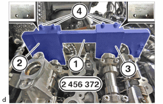
Position the setting gauge 0.5 ° (2) from the set of special tools 2 456 372 between the exhaust camshaft sub-assembly and the basic carrier (1) from the set of special tools 2 456 372.
- SST
- 09200-WA700
Position the setting gauge 0.7 ° (3) from the set of special tools 2 456 372 between the intake camshaft sub-assembly and the basic carrier (1) from the set of special tools 2 456 372.
- SST
- 09200-WA700
Tighten down bolts (4).
- Torque:
- 8.0 N*m (82 kgf*cm, 71 in.*lbf)
13070A
8.INSTALL CAMSHAFT TIMING EXHAUST GEAR ASSEMBLY
13050
9.INSTALL CAMSHAFT TIMING GEAR ASSEMBLY