B48 ENGINE MECHANICAL REAR CRANKSHAFT OIL SEAL INSTALLATION
PROCEDURE

 1.INSTALL TIMING CHAIN COVER OIL SEAL
- NOTICE:
- ·
Timing chain cover oil seal damage.
Touching the sealing lip (inner) and applying oil to the timing chain cover oil seal will lead to its destruction.
-Do not touch the sealing lip (inner) of the timing chain cover oil seal.
-Do not apply oil to the timing chain cover oil seal.
-Install the timing chain cover oil seal dry.
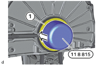
Fit special tool 0 496 137 (11 8 815) on the crankshaft.
- SST
- 09200-WA090
Carefully remove the timing chain cover oil seal (1) with a rotational movement via special tool 0 496 137 (11 8 815) until the timing chain cover oil seal is in flush contact with the timing gear case.
- SST
- 09200-WA090
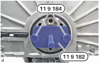
Secure special tool 0 494 029 (11 9 182) to the crankshaft using special tool 0 494 031 (11 9 184).
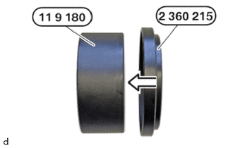
Connect special tool 2 360 215 to special tool 0 493 881 (11 9 180).
- SST
- 09200-WA060
09200-WA070
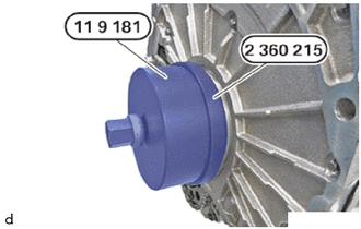
Draw in the timing chain cover oil seal using special tools 0 494 028 (11 9 181) and 2 360 215 in conjunction with special tool 0 494 030 (11 9 183).
- SST
- 09200-WA620
09200-WA060
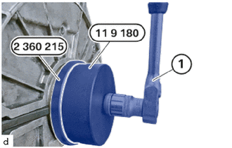
Screw in the timing chain cover oil seal using special tools 2 360 215 , 0 493 881 (11 9 180) and the tool (1) up to the stop.
- SST
- 09200-WA060
09200-WA070
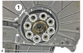
Using a tap, clean the threads of all of the screw holes.
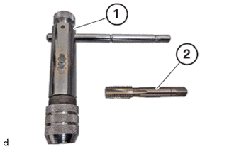
Install the tap to the tool holder of special tool 2 285 058.
- SST
- 09212-WA010
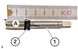
Using insulating tape, etc., mark the tap insertion depth.
- Insertion Depth A:
18 mm
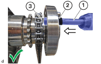
Twist in the tap in the direction indicated by the arrow until it reaches the specified insertion depth.
- Insertion Depth A:
18 mm
- HINT:
-
Make sure that the tap does not contact the timing chain.
- NOTICE:
-
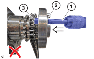
- ·
Do not insert the tap beyond the specified insertion depth.
·Be sure to handle the timing chain and timing gear carefully to avoid damaging them.
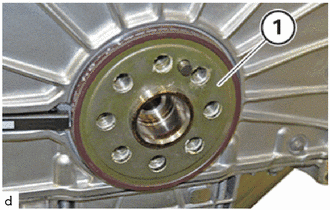
Ensure the correct mounting orientation of the No. 1 crank angle sensor plate (1).
Position the No. 1 crank angle sensor plate (1) on the crankshaft.
2.INSTALL DRIVE PLATE AND RING GEAR SUB-ASSEMBLY
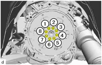
Replace bolts (1) to (8).
- HINT:
-
Clean screw thread.
Position the drive plate and ring gear sub-assembly and apply the bolts (1) to (8) hand-tight.
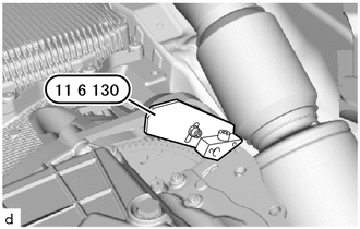
Check if the special tool 0 496 595 (11 6 130) is installed and positioned correctly.
- SST
- 09700-WA040
Install special tool 0 496 595 (11 6 130).
- SST
- 09700-WA040
Secure drive plate and ring gear sub-assembl ywith special tool 0496 595 (11 6 130).
- SST
- 09700-WA040
Tighten bolts (1) to (8).
- Torque:
- 45 N*m (459 kgf*cm, 33 ft.*lbf)
Using SST, tighten the bolts an additional 45°.
- SST
- 09900-WA010
- HINT:
-
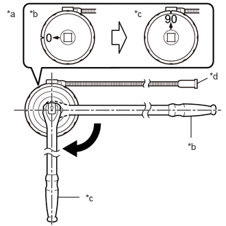 2.99,1.271 3.156,1.188 false 2.906,2.094 2.906,1.76 false 0.875,3 1.208,3 false 0.104,0.125 0.417,0.281 0.313,0.156 10 false *a 0.448,0.125 0.76,0.281 0.313,0.156 10 false *b 2.042,0.125 2.354,0.281 0.313,0.156 10 false *c 3.188,1.073 3.427,1.271 0.24,0.198 10 false *d 2.854,2.146 3.167,2.302 0.313,0.156 10 false *b 1.302,2.927 1.615,3.083 0.313,0.156 10 false *c
*a Example *b Before Tightening *c After Tightening *d Magnetic Portion
- ·
The magnetic portion is used to secure the gauge to the vehicle.
·After first adjusting the needle of the gauge to 0°, tighten to the specified angle.
·Perform the work procedure carefully so that the gauge, etc. does not become tilted.
Remove special tool 0 493 938 (11 9 260).
- SST
- 09200-WA200
35000
3.INSTALL AUTOMATIC TRANSMISSION ASSEMBLY