8HP51 AUTOMATIC TRANSMISSION / TRANSAXLE AUTOMATIC TRANSMISSION ASSEMBLY INSTALLATION
PROCEDURE

 1.INSTALL TORQUE CONVERTER
- CAUTION:
- ·
Damage to the driver of the impeller.
Failure to observe the installation instructions may lead to damage on the impeller driver.
-During installation, do not damage the torque converter radial shaft seal or ball bearing.
-Lock the torque converter correctly. Otherwise, the driver of the impeller may be damaged when the automatic transmission assembly is flange-mounted on the engine.
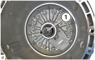
Replace the O-ring on the drive shaft (1).
- HINT:
-
When replacing the torque converter, use this procedure.
Push the torque converter onto the transmission shaft up to the limit position.
- HINT:
- ·
Press torque converter by hand into converter housing.
·At the same time, turn the torque converter until the recesses at the hub of the torque converter engage in the driver of the impeller.
·You can feel the torque converter slipping inward.
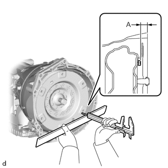
Determine the dimension between the contact surface and the outer edge of the torque converter threaded hole using a vernier caliper and straightedge.
- Standard:
Dimension (A) = Measured value is greater than 15 mm.
35000
2.TEMPORARILY TIGHTEN AUTOMATIC TRANSMISSION ASSEMBLY
- NOTICE:
- ·
Damage to the automatic transmission assembly.
Damage to the automatic transmission assembly through unapproved automatic transmission fluid.
-Use only the approved Automatic Gearbox Oil ATF 3+.
-After completion of repair work, check automatic transmission fluid level.
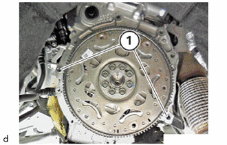
Check for correct fit of fitting sleeves (1).
- HINT:
-
Replace damaged fitting sleeves (1).
Rotate the torque converter until the bore hole of the torque converter is flush with bore hole in drive plate.
Install the automatic transmission assembly.
Fit the E10 bolts and E14 bolts and apply hand-tighten.
17119
3.INSTALL NO. 2 MANIFOLD STAY (for B48)
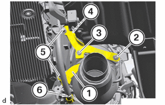
Position the No. 2 manifold stay (1).
Hand-tighten the bolts (5).
Replace the bolt (3) and nut (2).
Tighten the bolt (3) and nut (2).
- Torque:
- 19 N*m (194 kgf*cm, 14 ft.*lbf)
Mount the cable (4) of the front oxygen sensor on the No. 2 manifold stay (1).
Mount the cable (6) on the No. 2 manifold stay (1).
17119
4.INSTALL NO. 2 MANIFOLD STAY (for B58)
Insert and position the No. 2 manifold stay.
Hand-tighten the bolts.
- NOTICE:
- ·
Improper routing of the positive battery cable.
·Risk of short circuits!
-Route the positive battery cable without abrasions and do not trap.
Engage the starter cable in the clamps.
Engage the tab downward.
Replace nuts.
Tighten nuts.
- Torque:
- 28 N*m (286 kgf*cm, 21 ft.*lbf)
35000
5.FULLY TIGHTEN AUTOMATIC TRANSMISSION ASSEMBLY
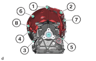
for B48:
Tighten the E10 bolts and E14 bolts in sequence (1) to (8).
- Torque:
- E10 bolt : 19 N*m (194 kgf*cm, 14 ft.*lbf)
- E14 bolt : 66 N*m (673 kgf*cm, 49 ft.*lbf)
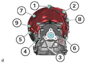
for B58:
Tighten the E10 bolts and E14 bolts in sequence (1) to (9).
- Torque:
- E10 bolt : 19 N*m (194 kgf*cm, 14 ft.*lbf)
- E14 bolt : 66 N*m (673 kgf*cm, 49 ft.*lbf)
6.REMOVE SPECIAL TOOL TO FIX THE TORQUE CONVERTER
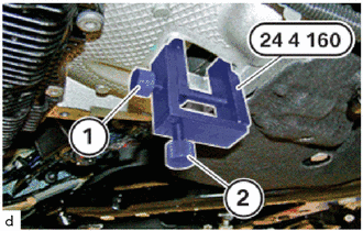
Release screw (1) and screw (2).
Remove special tool 0 494 451 (24 4 160).
- SST
- 09300-WA030
Install the transmission housing cover.
35128
7.INSTALL TRANSMISSION HOUSING UNDER COVER (for B48)
Install the transmission housing under cover.
Install the expanding rivet.
Install holder.
Tighten down the E10 bolt.
- Torque:
- 19 N*m (194 kgf*cm, 14 ft.*lbf)
8.INSTALL DRIVE PLATE AND TORQUE CONVERTER ASSEMBLY SETTING BOLT
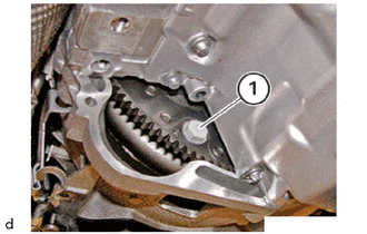
Replace the drive plate and torque converter assembly setting bolts.
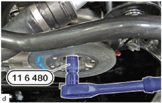
Turn the engine on the crankshaft pulley assembly with the special tool 0 493 380 (11 6 480) in the direction of rotation until a drive plate and torque converter assembly setting bolt (1) becomes visible in the recess.
- SST
- 09200-WA190
Tighten the drive plate and torque converter assembly setting bolts of the torque converter.
- Torque:
- 56 N*m (571 kgf*cm, 41 ft.*lbf)
- HINT:
-
Repeat this procedure for all drive plate and torque converter assembly setting bolts.
11401T
9.INSTALL CYLINDER BLOCK COVER (for B48)
10.INSTALL WIRE HARNESS
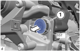
Remove the special tool 0 494 213 (24 2 390) from the sealing sleeve (1).
- SST
- 09300-WA100
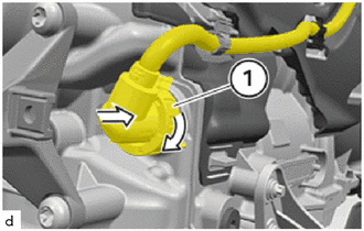
Slide the connector (1) on.
Twist the connector (1) in the direction of the arrow and lock.
82284A
11.CONNECT NO. 2 EARTH WIRE
Install the No. 2 earth wire.
Tighten nut.
- Torque:
- 19 N*m (194 kgf*cm, 14 ft.*lbf)
12.CONNECT OIL COOLER TUBE
Replace sealing rings.
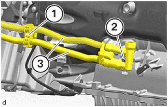
Position the oil cooler tubes on the automatic transmission assembly.
Tighten down the bolt (2).
- Torque:
- 8.0 N*m (82 kgf*cm, 71 in.*lbf)
Tighten down the T25 screw (1).
- Torque:
- 4.0 N*m (41 kgf*cm, 35 in.*lbf)
13.INSTALL PROPELLER SHAFT ASSEMBLY
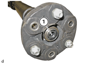
Check center No. 1 support bearing assembly for damage, replace if necessary.
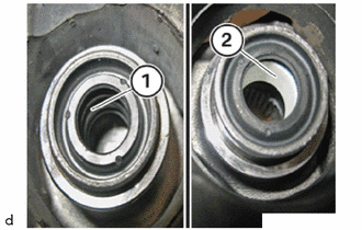
Apply a thin coat of Lubricant Olistamoly 2 LN 584 LO to the soft centering (1), if necessary.
- NOTICE:
-
Do not grease the hard centering (2).
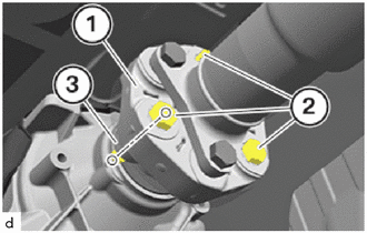
Replace the 18 mm bolts and 18 mm self-locking nuts.
Assemble the 18 mm bolts connections (2) of the flexible coupling (1) and the output flange (3) according to the self-affixed identification.
- NOTICE:
-
This should prevent a humming noise from the drive train during driving.
Hand-tighten 18 mm bolts (1) and 18 mm nuts (2), but do not tighten fully.
Position the center bearing.
- HINT:
-
Hand-tighten the bolts, but do not tighten fully.
Hand-tighten the bolts, but do not tighten fully.
Hold down the 18 mm bolts of the flexible coupling on the 18 mm nuts and tighten over the 18 mm bols.
- Torque:
- 55 N*m (561 kgf*cm, 41 ft.*lbf)
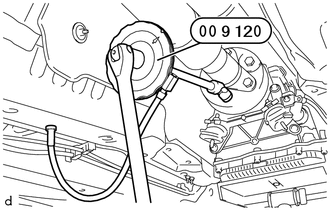
Using SST, tighten the 18 mm bolts and counter support them at the 18 mm nuts an additional 90°.
- SST
- 09900-WA010
- HINT:
- ·
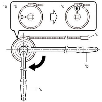 2.99,1.271 3.156,1.188 false 2.906,2.094 2.906,1.76 false 0.875,3 1.208,3 false 0.104,0.125 0.417,0.281 0.313,0.156 10 false *a 0.448,0.125 0.76,0.281 0.313,0.156 10 false *b 2.042,0.125 2.354,0.281 0.313,0.156 10 false *c 3.188,1.073 3.427,1.271 0.24,0.198 10 false *d 2.854,2.146 3.167,2.302 0.313,0.156 10 false *b 1.302,2.927 1.615,3.083 0.313,0.156 10 false *c
*a Example *b Before Tightening *c After Tightening *d Magnetic Portion
·The magnetic portion is used to secure the gauge to the vehicle.
·After first adjusting the needle of the gauge to 0°, tighten to the specified angle.
·Perform the work procedure carefully so that the gauge, etc. does not become tilted.
Tighten the bolts.
- Torque:
- 21.4 N*m (218 kgf*cm, 16 ft.*lbf)
57255
14.INSTALL REAR ENGINE MOUNTING MEMBER
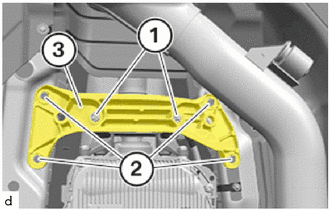
Install the rear engine mounting member (3).
Tighten the nuts (1).
- Torque:
- 19 N*m (194 kgf*cm, 14 ft.*lbf)
Tighten down the bolts (2).
- Torque:
- 19 N*m (194 kgf*cm, 14 ft.*lbf)
58152C
15.INSTALL FLOOR HEAT INSULATOR
Install the No. 1 floor heat Insulator and No. 2 floor heat Insulator.
Install the nuts and tighten.
- Torque:
- 3.0 N*m (31 kgf*cm, 27 in.*lbf)
58151
16.INSTALL FRONT NO. 1 FLOOR HEAT INSULATOR
17.INSTALL EXHAUST PIPE ASSEMBLY (for B48)
18.INSTALL EXHAUST PIPE ASSEMBLY (for B58)
58166A
19.INSTALL FRONT FLOOR COVER LH
58165C
20.INSTALL FRONT FLOOR COVER RH
- HINT:
-
Use the same procedure as for the LH side.
28100
21.INSTALL STARTER ASSEMBLY (for B48)
28100
22.INSTALL STARTER ASSEMBLY (for B58)
23.REMOVE ENGINE SUPPORT BRIDGE (for B58)
for Type A:
Click hereSuspension>FRONT SUSPENSION>FRONT SUSPENSION MEMBER>INSTALLATION
for Type B:
Click hereSuspension>FRONT SUSPENSION>FRONT SUSPENSION MEMBER>INSTALLATION
24.REMOVE ENGINE HANGER (for B58)
53826A
25.INSTALL FRONT FENDER UPPER PROTECTOR LH (for B58)
53825A
26.INSTALL FRONT FENDER UPPER PROTECTOR RH (for B58)
- HINT:
-
Use the same procedure as for the LH side.
12601B
27.INSTALL NO. 1 ENGINE COVER SUB-ASSEMBLY (for B58)
53440A
28.REMOVE AND INSTALL HOOD SUPPORT ASSEMBLY (for B58)
29.CONNECT CABLE TO NEGATIVE BATTERY TERMINAL (for B48)
30.CONNECT CABLE TO NEGATIVE BATTERY TERMINAL (for B58)
31.ADJUST AUTOMATIC TRANSMISSION FLUID LEVEL
32.INSPECT FOR AUTOMATIC TRANSMISSION FLUID LEAK
33.INSPECT FOR EXHAUST GAS LEAK
51219
34.INSTALL FRONT SUSPENSION MEMBER LOWER PROTECTOR
12371A
35.INSTALL REAR ENGINE MOUNTING INSULATOR
- HINT:
-
Perform this procedure only when replacement of the rear engine mounting insulator is necessary.
Install the rear engine mounting insulator.
Tighten nuts.
- Torque:
- 19 N*m (194 kgf*cm, 14 ft.*lbf)
12303
36.INSTALL REAR ENGINE MOUNTING BRACKET SUB-ASSEMBLY
- HINT:
-
Perform this procedure only when replacement of the rear engine mounting bracket sub-assembly is necessary.
Install the rear engine mounting bracket sub-assembly.
Tighten down the T55 bolts.
- Torque:
- 48 N*m (489 kgf*cm, 35 ft.*lbf)
37. ENCODE/PROGRAM CONTROL UNIT(S)
- NOTICE:
- ·
Use the most recent software version to prevent faults during programming/encoding.
·The battery voltage must not drop below 13.0 V during programming.
·Use only recommended chargers for a low-voltage vehicle electrical system.
·Do not exceed the maximum charging voltage of 14.8 V when charging the battery.
·When there is communication abnormality in the middle of work, control unit might be damaged.
·It may be necessary to perform the Action Plan several times.
Connect the battery charger to the vehicle.
Connect the diagnosis system with the vehicle.
Determine the action plan.
Service plan / Programming plan / Action plan / Calculate action plan
Accept and fully process the measures plan.
Service plan / Programming plan / Action plan / Perform action plan
Wait until programming/encoding has been completed.
- NOTICE:
-
When there is communication abnormality in the middle of work, control unit might be damaged.
Carry out vehicle test.
Vehicle management / Troubleshooting / Fault memory / Calculate test plan
Delete the fault memory.
Vehicle management / Troubleshooting / Fault memory / Delete fault memory
Disconnect the diagnosis system from the vehicle.
Disconnect the battery charger from the vehicle.