STEERING GEAR / LINKAGE TIE ROD REMOVAL
CAUTION / NOTICE / HINT
- HINT:
- ·
Use the same procedure for the RH side and LH side.
·The following procedure is for the LH side.
PROCEDURE

 1.REMOVE FRONT WHEEL
51219
2.REMOVE FRONT SUSPENSION MEMBER LOWER PROTECTOR
45047
3.REMOVE TIE ROD END SUB-ASSEMBLY
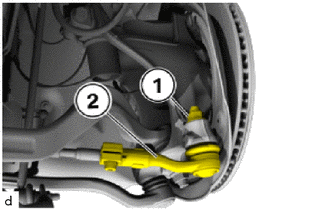
Loosen the nut (1).
- HINT:
-
If necessary, counter-hold the T40 "TORX" socket wrench.
Pull the tie rod end sub-assembly (2) off the steering knuckle LH.
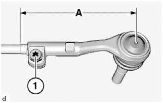
Determine and write down the dimension (A).
- HINT:
-
The dimension (A) is needed to simplify the toe adjustment at the front axle.
Slacken T50 bolt (1).
Unscrew tie rod end sub-assembly.
45536
4.REMOVE STEERING RACK BOOT
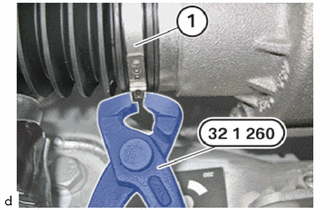
Cut diagonally across the clamp (1) using special tool 0 494 152 (32 1 260).
- SST
- 09200-WA590
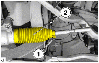
Remove the clip (1).
Pull steering rack boot (2) off the steering gear assembly.
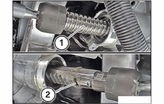
Check the poslished surface of spindle (1) or rack (2) for damage.
45470
5.REMOVE TIE ROD ASSEMBLY
- NOTICE:
-
In order to avoid damage of the steering shaft and its bearing, the steering shaft must be positioned in the steering gear assembly far as possible.
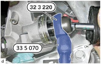
Release the tie rod assembly from the steering shaft of the steering gear assembly using special tool 0 496 483 (32 3 220) and 0 495 554 (33 5 070).
- SST
- 09600-WA040
09900-WA040