AXLE AND DIFFERENTIAL DIFFERENTIAL MOUNT CUSHION INSTALLATION
PROCEDURE

 1.INSTALL REAR NO. 1 DIFFERENTIAL MOUNT CUSHION
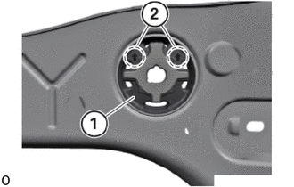
Position the rear No. 1 differential mount cushion (1) before assembly so that the arrow (2) is pointing upwards.
- HINT:
-
A mark can be made on the outer area of the rear No. 1 differential mount cushion (1) to check the assembly position of the rear No. 1 differential mount cushion.
- Position of the rear No. 1 differential mount cushion:
- Permissible rotation in relation to the vertical:
-5° to 5°
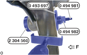
Position the rear No. 1 differential mount cushion on the rear suspension member sub-assembly using the special tools (2 304 560 , 0 493 697 (33 3 233), 0 494 982 (33 4 466) and 0 494 981 (33 4 465)).
- SST
- 09500-WA150
09500-WA320
09500-WA330
- HINT:
-
Respect direction of travel (F).
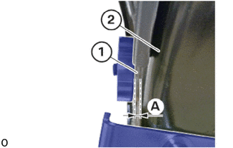
Pull rear No. 1 differential mount cushion (1) into the rear suspension member sub-assembly (2) using special tool until the protrusion (A) is reached.
- HINT:
-
Prepare protrusion (A), which has been determined before removing the rear No. 1 differential mount cushion.
Remove special tools.
41651A
2.INSTALL REAR NO. 2 DIFFERENTIAL MOUNT CUSHION
- HINT:
-
Use the same procedure for the opposite side.
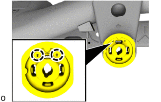
Position the rear No. 2 differential mount cushion before installation so that the arrows in the marked areas point upwards.
- HINT:
-
A mark can be made on the outer area of the rear No. 2 differential mount cushion to check the installation position of the rear No. 2 differential mount cushion.
- Position of the rear No. 2 differential mount cushion:
- Permissible rotation in relation to the vertical:
-7° to 7°
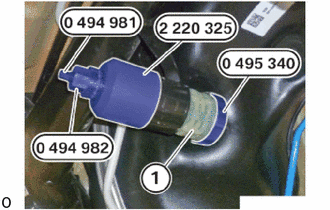
Pull the rear No. 2 differential mount cushion into the rear suspension member sub-assembly using special tools (0 495 340 (33 4 351), 2 220 325 (33 0 181), 0 494 981 (33 4 465) and 0 494 982 (33 4 466)).
- SST
- 09500-WA150
09500-WA280
09500-WA290
- HINT:
-
Ensure that the special tool (2 220 325 (33 0 181) is correctly positioned on the rear suspension member sub-assembly.
Remove special tools.
51206A
3.INSTALL REAR SUSPENSION MEMBER SUB-ASSEMBLY