B58 FUEL FUEL PUMP INSTALLATION
PROCEDURE

 1. FOR REPLACEMENT: PREPARING THE FUEL DELIVERY UNIT FOR INSTALLATION
- HINT:
-
All new delivery units are delivered with the stationary heating system in the equipment specification.
-
For these vehicles, the connection on the flange lid must be closed with a locking coupling.
-
Locking coupling must be ordered separately, see Electronic Parts Catalog.
For vehicles without auxiliary heater, the intake manifold for the auxiliary heater must be removed.
Separate intake manifold for auxiliary heater (1) in the area (2) at the connection of the service cap using suitable tool (diagonal cutting pliers).
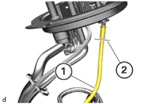
Separated intake manifold can be disposed of.
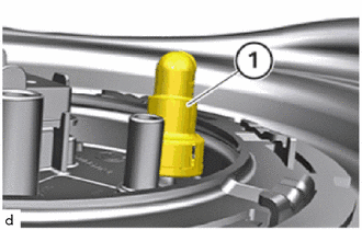
Place and lock the lock coupling (1) on the connection of the fuel line for the stationary heating system.
77020A
2. FUEL SUCTION TUBE WITH PUMP AND GAGE ASSEMBLY
- CAUTION:
-
Working on fuel system.
-
Risk of fire! Danger of explosion!
- ·
When working on the fuel system, make sure that the workbay is sufficiently ventilated, e.g. using extraction unit.
·Tightly seal off open lines and connections; collect any leakage fuel directly at the point of exit.
·No fire, sparks, open flames or smoking.
- HINT:
-
Collect and dispose of emerging fluids. Observe country-specific waste disposal regulations.
Thread the fuel feed unit (1) in the direction of the arrow from above and lock it.
Care must be taken to ensure correct locking of the fuel delivery unit in the receptacle!
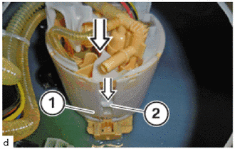
Lock the lock (2) in the direction of the arrow downwards.
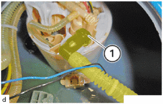
Apply and lock the quick release (1).
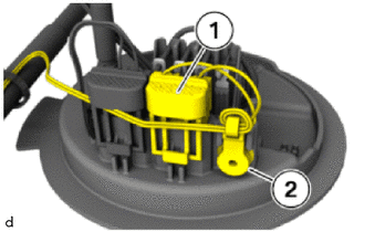
Connect and lock connector (1).
Clip in the cable holder (2).
- NOTICE:
-
To provide a better overview: Schematic diagram with partially hidden components.
Replace sealing ring (1).
- NOTICE:
-
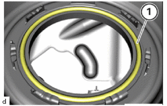
-
Schematic diagram is for example purposes. Some parts may differ in certain details.
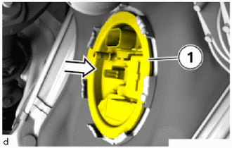
Install flange cover (1) in direction of arrow.
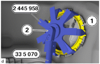
Place special tool 2 445 958 on lock ring (1).
- SST
- 09800-WA290
Connect special tool 0 495 554 (33 5 070) with the standard tool (2) and place on special tool 2 445 958.
- Standard tools:
Plug-in reversible ratchet 1/2 inch
- SST
- 09800-WA290 09900-WA040
Tighten locking ring (1) clockwise.
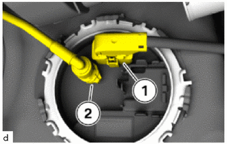
Connect and lock connector (1).
Apply and lock fuel supply line (2).
58151
3.INSTALL FRONT NO.1 FLOOR HEAT INSULATOR