DRIVE SHAFT / PROPELLER SHAFT PROPELLER SHAFT ASSEMBLY INSTALLATION
PROCEDURE

 37100
1.INSTALL PROPELLER SHAFT ASSEMBLY WITH CENTER BEARING
- NOTICE:
- ·
Damage to the propeller shaft assembly with center bearing during installation.
·Non-observance of the installation guidelines for the propeller shaft on the rear axle differential may cause severe damage.
-Always replace the insert nut on the rear axle differential. Screw locking must be available.
-Strictly observe a minimum hardening time of 3 hours after having screwed in the insert nut. The hardening time may be longer at lower temperatures.
Installation sequence:
Position propeller shaft assembly with center bearing on automatic transmission.
Position the propeller shaft assembly with center bearing at the rear axle differential.
Position center No. 1 support bearing assembly.
Screw-fastening sequence:
Insert nut
Flexible coupling to automatic transmission
Center No. 1 support bearing assembly
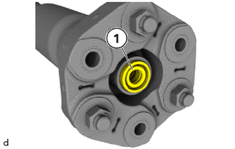
Check propeller shaft spline sleeve (1) for damage; replace if necessary.
Coat the propeller shaft spline sleeve (1) of the propeller shaft assembly with center bearing with Lubricant Olistamoly 2 LN 584 LO.
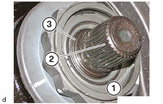
Clean all residue from the recessed collar (1) of the flange nut and the gearing (2) on the bevel gear (3) and degrease the components.
Coat the collar insert (1) of the propeller shaft assembly with center bearing with Lubricating Grease Optitemp HT 1 LF.
- NOTICE:
- ·
Damage to the output flange.
·Failure to observe the greasing specifications may lead to damage on the output flange.
-Do not contaminate the thread of the output flange with grease.
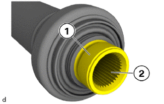
Remove adhesive residue from the thread (1) of the propeller shaft hub and clean it.
Clean the hub gearing (2) and subsequently coat it with Lubricating Grease Optitemp HT 1 LF.
Replace insert nut.
Insert the insert nut.
Replace the seal and the retaining clip.
Position the seal and the retaining clip.
In order to avoid a humming noise of the drivetrain after reinstalling the propeller shaft assembly with center bearing: It is essential to reassemble the three-hole flange with the flexible coupling in the highlighted position.
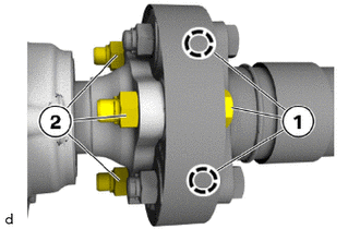
Replace the 18 mm bolts and the 18 mm nuts.
Temporarily install the propeller shaft assembly with center bearing with the 18 mm bolts and 18 mm nuts.
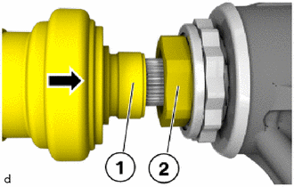
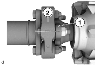
Push the propeller shaft assembly with center bearing (1) in the direction of the arrow against the insert nut (2) up to the limit position.
Manually screw on and tighten the insert nut (2) onto the propeller shaft assembly with center bearing (1) by a minimum of two threads.
center mount with TOP marking:
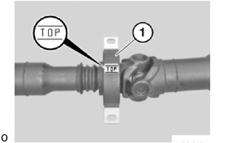
The center mount (1) must be installed with the TOP marking at the top in the gearbox tunnel.
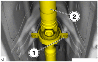
Position the propeller shaft assembly with center bearing (2).
Position bolts (1).
Secure the propeller shaft assembly with center bearing against twisting at the central universal joint using a suitable tool.
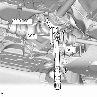
| *a | Torque Wrench Fulcrum Length |
Tighten the insert nut in anti-clockwise direction using SST 0 496 959 (33 0 080) and SST.
- SST
- 09900-WA280
09500-WA170
- Torque:
100 N*m (1020 kgf*cm, 74 ft.*lbf)
- NOTICE:
- ·
Damage to the flange nut.
·Failure to observe the installation specifications may lead to serious damage to the flange nut and the rear axle differential.
-Do not use the double hexagon flange nut as counter support.
-Screw in the insert nut within 5 minutes.
- HINT:
-
Calculate the torque wrench reading when changing the fulcrum length of the torque wrench.
-
Click hereGeneral>INTRODUCTION>REPAIR INSTRUCTION>PRECAUTION
Screw the insert nut within 5 min.
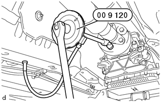
Hold down the 18 mm bolts of the flexible coupling on the 18 mm nuts and tighten over the 18 mm bolts.
- SST
- 09900-WA010
- Torque:
- 55 N*m (561 kgf*cm, 41 ft.*lbf)
Tighten the 18 mm bolts an additional 90° and counter support them at the 18 mm nuts.
- HINT:
- ·
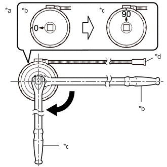 2.99,1.271 3.156,1.188 false 2.906,2.094 2.906,1.76 false 0.875,3 1.208,3 false 0.104,0.125 0.417,0.281 0.313,0.156 10 false *a 0.448,0.125 0.76,0.281 0.313,0.156 10 false *b 2.042,0.125 2.354,0.281 0.313,0.156 10 false *c 3.188,1.073 3.427,1.271 0.24,0.198 10 false *d 2.854,2.146 3.167,2.302 0.313,0.156 10 false *b 1.302,2.927 1.615,3.083 0.313,0.156 10 false *c
*a Example *b Before Tightening *c After Tightening *d Magnetic Portion
·The magnetic portion is used to secure the gauge to the vehicle.
·After first adjusting the needle of the gauge to 0°, tighten to the specified angle.
·Perform the work procedure carefully so that the gauge, etc. does not become tilted.
Tighten the bolts.
- Torque:
- 21.4 N*m (218 kgf*cm, 16 ft.*lbf)
57255
2.INSTALL REAR ENGINE MOUNTING MEMBER
58151
3.INSTALL FRONT NO. 1 FLOOR HEAT INSULATOR
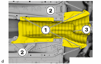
Position the front No. 1 floor heat insulator of the tank (3).
Tighten the sheet metal nuts (2).
- Torque:
- 3.0 N*m (31 kgf*cm, 27 in.*lbf)
Tighten the screws (1).
- Torque:
- 2.6 N*m (27 kgf*cm, 23 in.*lbf)
4.INSTALL EXHAUST PIPE ASSEMBLY (for B48)
5.INSTALL EXHAUST PIPE ASSEMBLY (for B58)
58166A
6.INSTALL FRONT FLOOR COVER LH
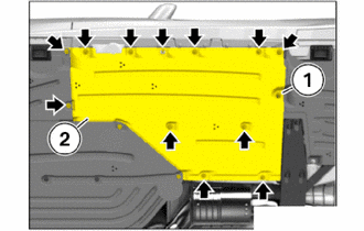
Insert the front floor cover LH (2).
Tighten all screws (arrows) and nut (1).
- Torque:
- 2.6 N*m (27 kgf*cm, 23 in.*lbf)
58165C
7.INSTALL FRONT FLOOR COVER RH
- HINT:
-
Use the same procedure as for the LH side.
50819
8.INSTALL FRONT FLOOR COVER