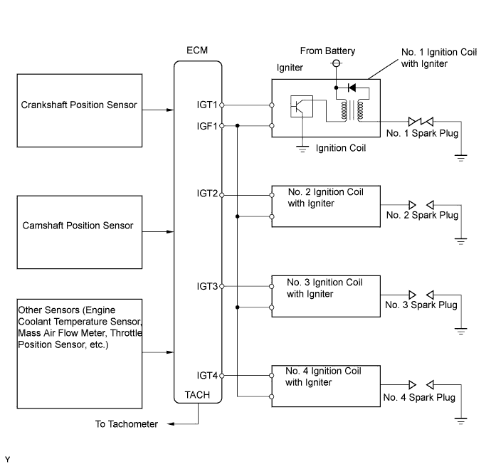
DTC P0351 Ignition Coil "A" Primary / Secondary Circuit |
DTC P0352 Ignition Coil "B" Primary / Secondary Circuit |
DTC P0353 Ignition Coil "C" Primary / Secondary Circuit |
DTC P0354 Ignition Coil "D" Primary / Secondary Circuit |
| DTC No. | DTC Detection Conditions | Trouble Areas |
| P0351 P0352 P0353 P0354 | No IGF signal to ECM while engine running (1 trip detection logic) |
|
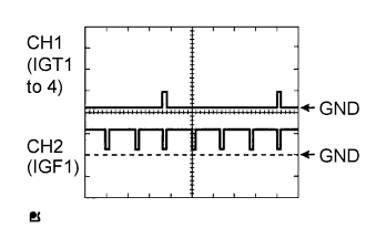
| Items | Contents |
| Terminals | CH1: IGT1, IGT2, IGT3, IGT4 - E1 CH2: IGF1 - E1 |
| Equipment Settings | 2 V/Division, 20 ms/Division |
| Conditions | Cranking or idling |
| Related DTCs | P0351: Igniter (cylinder 1) malfunction P0352: Igniter (cylinder 2) malfunction P0353: Igniter (cylinder 3) malfunction P0354: Igniter (cylinder 4) malfunction |
| Required Sensors/Components (Main) | Igniter |
| Required Sensors/Components (Related) | Crankshaft position sensor |
| Frequency of Operation | Continuous |
| Duration | 0.256 seconds and 4 sparks |
| MIL Operation | Immediate |
| Sequence of Operation | None |
| Monitor runs whenever following DTCs not present | None |
| Either of following conditions met | - |
| Engine RPM | 1,500 rpm or less |
| Starter | OFF |
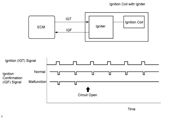
| IGF signal | ECM does not receive any IGF signal despite ECM sending IGT signal to igniter |
| IGF signal | Igniter transmits IGF signal when it receives IGT signal from ECM |
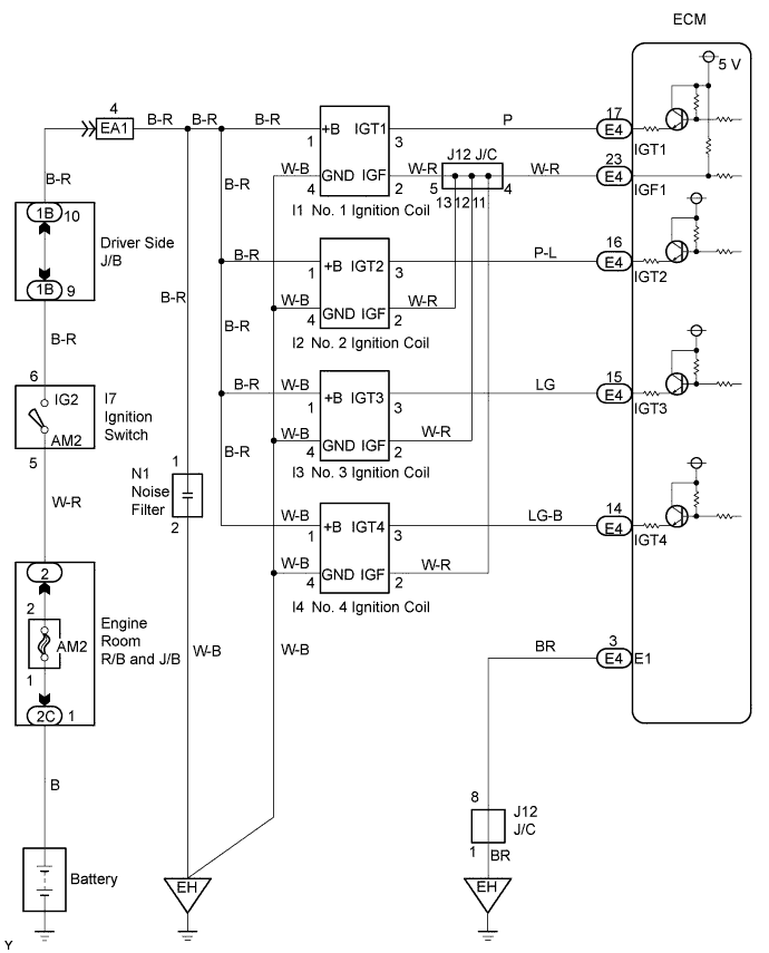
| 1.CHECK WHETHER DTC OUTPUT RECURS (DTC P0351, P0352, P0353 OR P0354) |
Connect an intelligent tester to the DLC3.
Turn the ignition switch to ON.
Turn the tester ON.
Clear DTCs (Click here).
Shuffle arrangement of the ignition coils with igniters (among No. 1 to No. 4 cylinders).
Perform a simulation test.
Check DTCs displayed on the tester.
| Display (DTC Output) | Proceed To |
| Same DTC output | A |
| Other ignition coil DTC output | B |
|
| ||||
| A | |
 |
| 2.INSPECT ECM (IGT1, IGT2, IGT3, IGT4 AND IGF1 SIGNAL) |
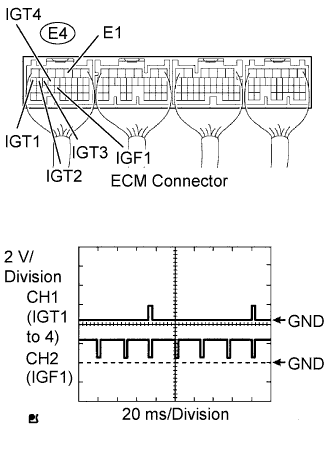 |
Inspect the ECM using an oscilloscope.
While cranking or idling, check the waveform between the terminals of the E4 ECM connector.
| Tester Connections | Specified Conditions |
| IGT1 (E4-17) - E1 (E4-3) | Correct waveform shown |
| IGT2 (E4-16) - E1 (E4-3) | Correct waveform shown |
| IGT3 (E4-15) - E1 (E4-3) | Correct waveform shown |
| IGT4 (E4-14) - E1 (E4-3) | Correct waveform shown |
| IGF1 (E4-23) - E1 (E4-3) | Correct waveform shown |
|
| ||||
| OK | |
|
| 3.CHECK HARNESS AND CONNECTOR (IGNITION COIL ASSEMBLY - ECM) |
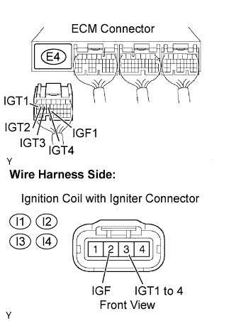 |
Disconnect the ignition coil with igniter connector.
Disconnect the E4 ECM connector.
Check the resistance.
| Tester Connections | Specified Conditions |
| IGF (I1-2) - IGF1 (E4-23) | Below 1 Ω |
| IGF (I2-2) - IGF1 (E4-23) | Below 1 Ω |
| IGF (I3-2) -IGF1 (E4-23) | Below 1 Ω |
| IGF (I4-2) - IGF1 (E4-23) | Below 1 Ω |
| Tester Connections | Specified Conditions |
| IGT1 (I1-3) - IGT1 (E4-17) | Below 1 Ω |
| IGT2 (I2-3) - IGT2 (E4-16) | Below 1 Ω |
| IGT3 (I3-3) - IGT3 (E4-15) | Below 1 Ω |
| IGT4 (I4-3) - IGT4 (E4-14) | Below 1 Ω |
| Tester Connections | Specified Conditions |
| IGF (I1-2) or IGF1 (E4-23) - Body ground | 10 kΩ or higher |
| IGF (I2-2) or IGF1 (E4-23) - Body ground | 10 kΩ or higher |
| IGF (I3-2) or IGF1 (E4-23) - Body ground | 10 kΩ or higher |
| IGF (I4-2) or IGF1 (E4-23) - Body ground | 10 kΩ or higher |
| Tester Connections | Specified Conditions |
| IGT1 (I1-3) or IGT1 (E4-17) - Body ground | 10 kΩ or higher |
| IGT2 (I2-3) or IGT2 (E4-16) - Body ground | 10 kΩ or higher |
| IGT3 (I3-3) or IGT3 (E4-15) - Body ground | 10 kΩ or higher |
| IGT4 (I4-3) or IGT4 (E4-14) - Body ground | 10 kΩ or higher |
Reconnect the ECM connector.
Reconnect the ignition coil with igniter connector.
|
| ||||
| OK | |
|
| 4.INSPECT IGNITION COIL ASSEMBLY (POWER SOURCE) |
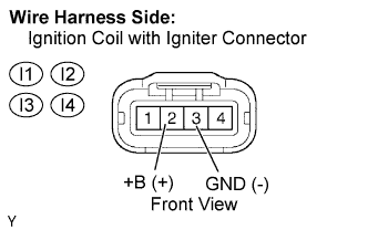 |
Disconnect the ignition coil with igniter connector.
Check the resistance.
| Tester Connections | Specified Conditions |
| GND (I1-4) - Body ground | Below 1 Ω |
| GND (I2-4) - Body ground | Below 1 Ω |
| GND (I3-4) - Body ground | Below 1 Ω |
| GND (I4-4) - Body ground | Below 1 Ω |
Turn the ignition switch to ON.
Measure the voltage between the terminals of the wire harness side connector.
| Tester Connections | Specified Conditions |
| +B (I1-1) - GND (I1-4) | 9 to 14 V |
| +B (I2-1) - GND (I2-4) | 9 to 14 V |
| +B (I3-1) - GND (I3-4) | 9 to 14 V |
| +B (I4-1) - GND (I4-4) | 9 to 14 V |
Reconnect the ignition coil with igniter connector.
|
| ||||
| NG | |
|
| 5.CHECK HARNESS AND CONNECTOR (IGNITION COIL ASSEMBLY - IGNITION SWITCH) |
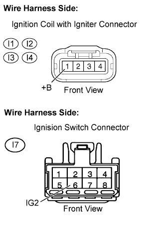 |
Disconnect the ignition coil with igniter connector.
Disconnect the I7 ignition switch connector.
Check the resistance.
| Tester Connections | Specified Conditions |
| +B (I1-1) -IG2 (I7-6) | Below 1 Ω |
| +B (I2-1) - IG2 (I7-6) | Below 1 Ω |
| +B (I3-1) - IG2 (I7-6) | Below 1 Ω |
| +B (I4-1) - IG2 (I7-6) | Below 1 Ω |
| Tester Connections | Specified Conditions |
| +B (I1-1) or IG2 (I7-6) - Body ground | 10 kΩ or higher |
| +B (I2-1) or IG2 (I7-6) - Body ground | 10 kΩ or higher |
| +B (I3-1) or IG2 (I7-6) - Body ground | 10 kΩ or higher |
| +B (I4-1) or IG2 (I7-6) - Body ground | 10 kΩ or higher |
Reconnect the ignition coil with igniter connector.
Reconnect the ignition switch connector.
|
| ||||
| OK | ||
 | ||
| ||
