| B |  |
| GO TO DTC CHART |
DTC P0756 Shift Solenoid "B" Performance (Shift Solenoid Valve S2) |
| DTC No. | DTC Detection Conditions | Trouble Areas |
| P0756 | S2 stuck OFF malfunction*2: Shifting to 1st and 4th gears is impossible. The ECM determines that there is a malfunction when the following conditions are met: (a) When the ECM directs the gearshift to switch to 2nd gear, the actual gear is shifted to 1st. (b) When the ECM directs the gearshift to switch to 3rd gear, the actual gear is shifted to 4th. |
|
| P0756 | S2 stuck ON malfunction*1: The vehicle starts in 2nd gear and shifting to 3rd gear is impossible. The ECM determines that there is a malfunction when the following conditions are met: (a) When the ECM directs the gearshift to switch to 1st gear, the actual gear is shifted to 2nd. (b) When the ECM directs the gearshift to switch to 4th gear, the actual gear is shifted to 3rd. |
|
| Gearshift controlled by ECM | 1st | 2nd | 3rd | 4th |
|
*1: Actual gear position under S2 stuck ON malfunction | 2nd | 2nd | 3rd | 3rd |
|
*2: Actual gear position under S2 stuck OFF malfunction | 1st | 1st | 4th | 4th |
| Related DTCs | P0756: Shift solenoid valve S2/OFF malfunction Shift solenoid valve S2/ON malfunction |
| Required sensors/Components | Shift solenoid valve S2 |
| Frequency of operation | Continuous |
| Duration | 1.0 second |
| MIL operation | 2 driving cycles |
| Sequence of operation | None |
| The monitor will run whenever the following DTCs are not present. | P0115 - P0118 (ECT sensor) P0125 (Insufficient ECT for closed loop) P0500 (VSS) P0748 - P0798 (Trans solenoid (range)) |
| Shift solenoid "A" (S1) circuit Shift solenoid "B" (S2) circuit ECT (Engine Coolant Temperature) sensor circuit Input speed sensor circuit Output speed sensor circuit | There is no malfunction in the sensor circuits shown on the left |
| Transmission shift position | "D" |
| ECT (Engine Coolant Temperature) | 40°C (104°F) or more |
| Spark advance from max. retard timing by knock control | 0°CA or more |
| Engine | Running |
| ECM selected gear | 2nd |
| Vehicle speed | 6.2 mph (10 km/h) or more |
| Throttle valve opening angle | 6.5 % or more at engine speed of 2,000 rpm (Conditions vary with engine speed) |
| ECM selected gear | 3rd |
| Vehicle speed | 6.2 mph (10 km/h) or more |
| Throttle valve opening angle | 6.5 % or more at engine speed of 2,000 rpm (Conditions vary with engine speed) |
| ECM selected gear | 4th |
| Vehicle speed | 6.2 mph (10 km/h) or more |
| Throttle valve opening angle | 6.5 % or more at engine speed of 2,000 rpm (Conditions vary with engine speed) |
| ECM selected gear | 1st |
| Vehicle speed | 6.2 mph (10 km/h) or more and Less than 24.8 mph (40 km/h) |
| Throttle valve opening angle | 6.5 % or more at engine speed of 2,000 rpm (Conditions vary with engine speed) |
| ECM selected gear | 3rd |
| Vehicle speed | 6.2 mph (10 km/h) or more |
| Throttle valve opening angle | 6.5 % or more at engine speed of 2,000 rpm (Conditions vary with engine speed) |
| ECM selected gear | 4th |
| Vehicle speed | 6.2 mph (10 km/h) or more |
| Throttle valve opening angle | 6.5 % or more at engine speed of 2,000 rpm (Conditions vary with engine speed) |
| Input speed/Output speed (NC0/SP2) | 2.63 or more and 3.20 or less (This means actual gear is 1st) |
| Input speed/Output speed (NC0/SP2) | 0.00 or more and 0.22 or less (This means actual gear is 4th) |
| Input speed/Output speed (NC0/SP2) | 0.00 or more and 0.22 or less (This means actual gear is 4th) |
| Input speed/Output speed (NC0/SP2) | 1.40 or more and 1.67 or less (This means actual gear is 2nd) |
| Input speed/Output speed (NC0/SP2) | 0.93 or more and 1.07 or less (This means actual gear is 3rd) |
| Input speed/Output speed (NC0/SP2) | 0.93 or more and 1.07 or less (This means actual gear is 3rd) |
| ACTIVE TEST |
Warm up the engine.
Turn the ignition switch off.
Connect the intelligent tester together with the CAN VIM (controller area network vehicle interface module) to the DLC3.
Turn the ignition switch to the ON position.
Push the "ON" button of the tester.
Select the items "DIAGNOSIS/ ENHANCED OBD II/ ACTIVE TEST/ SHIFT".
According to the display on the tester, perform the "ACTIVE TEST".
| Item | Test Details | Diagnostic Note |
| SHIFT | [Test Details] Operate the shift solenoid valve and set each shift position by manually. [Vehicle Condition]
| Possible to check the operation of the shift solenoid valves. |
| Gearshift controlled by ECM | 1st | 2nd | 3rd | 4th |
| Shift solenoid valve S2 | OFF | ON | ON | OFF |
| 1.CHECK ANY OTHER DTCS OUTPUT (IN ADDITION TO DTC P0756) |
Connect the intelligent tester to the DLC3.
Turn the ignition switch to the ON position and push the intelligent tester main switch ON.
Select the items "DIAGNOSIS/ ENHANCED OBD II/ DTC INFO/ CURRENT CODES".
Read the DTCs using the intelligent tester.
| Display (DTC Output) | Proceed to |
| Only "P0756" is output | A |
| "P0756" and other DTCs | B |
|
| ||||
| A | |
 |
| 2.INSPECT SHIFT SOLENOID VALVE S2 |
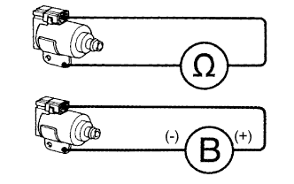 |
Remove the shift solenoid valve S2.
Measure the resistance.
| Tester Connection | Specified Condition |
| Solenoid Connector (S2) - Solenoid Body (S2) | 11 to 15 Ω at 20°C (68°F) |
Connect positive (+) lead to the terminal of the solenoid connector, negative (-) lead to the solenoid body.
|
| ||||
| OK | |
|
| 3.INSPECT TRANSMISSION VALVE BODY ASSEMBLY |
|
| ||||
| OK | ||
 | ||
| ||