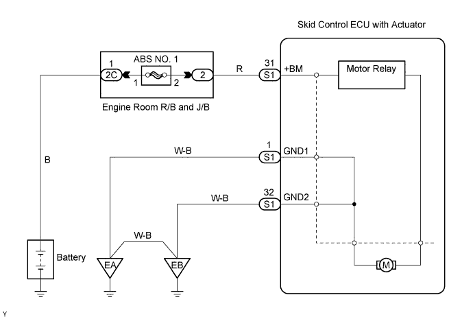
DTC C0273/13 Open or Short Circuit in ABS Motor Relay Circuit |
DTC C0274/14 Short to B+ in ABS Motor Relay Circuit |
| DTC No. | DTC Detecting Conditions | Trouble Areas |
| C0273/13 | When either of following (1 or 2) detected: 1. Both of following conditions continue for at least 0.2 seconds.
|
|
| C0274/14 | The following condition continues for at least 4 seconds.
|
|
| 1.PERFORM ACTIVE TEST BY INTELLIGENT TESTER (ABS MOTOR RELAY) |
Connect the intelligent tester to the DLC3.
Turn the ignition switch to the ON position.
Turn the intelligent tester ON.
Select the DATA LIST mode on the intelligent tester.
Check the operation sound of the ABS motor when operating it with the intelligent tester.
| Item | Vehicle Condition / Test Details | Diagnostic Note |
| ABS MOT RELAY | Turns ABS motor relay ON/OFF | Operation of motor can be heard |
|
| ||||
| OK | |
 |
| 2.RECONFIRM DTC |
Clear the DTCs (Click here).
Drive the vehicle at 6mph (10 km/h) or more to activate initial check.
Check if the same DTCs are detected.
| Result | Proceed to |
| DTC output | A |
| DTC not output | B |
|
| ||||
| A | |
|
| 3.INSPECT SKID CONTROL ECU TERMINAL VOLTAGE (BM+ - GND1, GND2) |
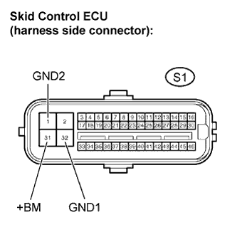 |
Disconnect the skid control ECU connector.
Measure the voltage.
| Tester Connection | Condition | Specified Condition |
| S1-31 (+BM) - S1-1, 32 (GND1, GND2) | Always | 10 to 14 V |
Reconnect the skid control ECU connector.
|
| ||||
| OK | ||
 | ||
| ||

