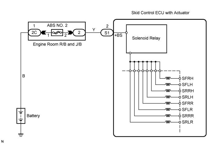
DTC C0278/11 Open or Short Circuit in ABS Solenoid Relay Circuit |
DTC C0279/12 Short to B+ in ABS Solenoid Relay Circuit |
| DTC No. | DTC Detecting Conditions | Trouble Areas |
| C0278/11 | When either of following (1 or 2) detected: 1. Both of following conditions continue for at least 0.2 seconds.
|
|
| C0279/12 | The following condition continues for at least 0.2 seconds.
|
|
| 1.INSPECT SKID CONTROL ECU TERMINAL VOLTAGE (+BS - GND1, GND2) |
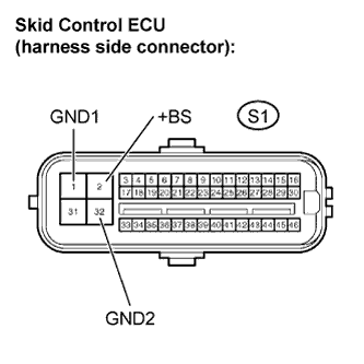 |
Disconnect the skid control ECU connector.
Measure the voltage.
| Tester Connection | Condition | Specified Condition |
| S1-2 (BS+) - S1-1,32 (GND1, GND2) | Always | 10 to 14 V |
Reconnect the skid control ECU connector.
|
| ||||
| OK | |
 |
| 2.RECONFIRM DTC |
Clear the DTCs (Click here).
Drive the vehicle at 6 mph (10 km/h) or more to activate initial check.
Check if the same DTCs are detected.
| Result | Proceed to |
| DTC output | A |
| DTC not output | B |
|
| ||||
| A | ||
 | ||
| ||
