 |
FRONT DOOR (w/ Power Window) > ADJUSTMENT |
|
| 1. INSPECT FRONT DOOR PANEL SUB-ASSEMBLY LH (for Double Cab) |
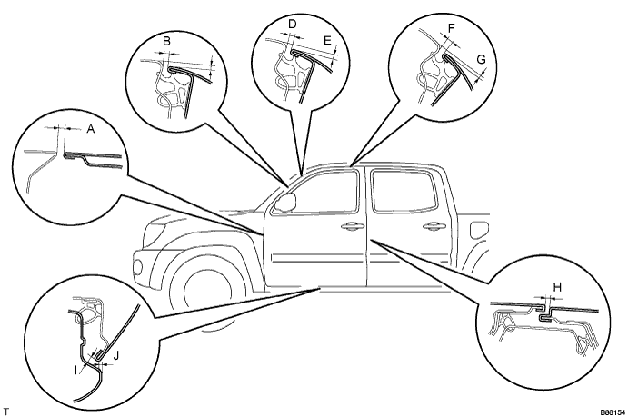
| Area | Measurement | Area | Measurement |
| A | 4.6 +- 1.5 mm (0.181 +- 0.059 in.) | F | 5.0 +- 1.5 mm (0.197 +- 0.059 in.) |
| B | 5.0 +- 1.5 mm (0.197 +- 0.059 in.) | G | 1.9 +- 1.5 mm (0.075 +- 0.059 in.) |
| C | 3.0 +- 1.5 mm (0.118 +- 0.059 in.) | H | 5.0 +- 1.5 mm (0.197 +- 0.059 in.) |
| D | 5.0 +- 1.5 mm (0.197 +- 0.059 in.) | I | 5.0 +- 1.5 mm (0.197 +- 0.059 in.) |
| E | 2.7 +- 1.5 mm (0.106 +- 0.059 in.) | J | 2.0 +- 1.5 mm (0.079 +- 0.059 in.) |
| 2. INSPECT FRONT DOOR PANEL SUB-ASSEMBLY LH (for Access Cab) |
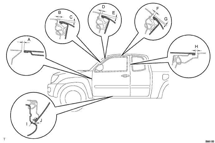
Check that the clearance measurements of areas A to J are within the standard ranges.
| Area | Measurement | Area | Measurement |
| A | 4.6 +- 1.5 mm (0.181 +- 0.059 in.) | F | 5.0 +- 1.5 mm (0.197 +- 0.059 in.) |
| B | 5.0 +- 1.5 mm (0.197 +- 0.059 in.) | G | 1.9 +- 1.5 mm (0.075 +- 0.059 in.) |
| C | 3.0 +- 1.5mm (0.118 +- 0.059 in.) | H | 6.0 +- 1.5mm (0.236 +- 0.059 in.) |
| D | 5.0 +- 1.5 mm (0.197 +- 0.059 in.) | I | 5.0 +- 1.5mm (0.197 +- 0.059 in.) |
| E | 2.7 +- 1.5mm (0.106 +- 0.059 in.) | J | 2.0 +- 1.5mm (0.079 +- 0.059 in.) |
| 3. ADJUST FRONT DOOR PANEL SUB-ASSEMBLY LH |
Disconnect the cable from the negative battery terminal.
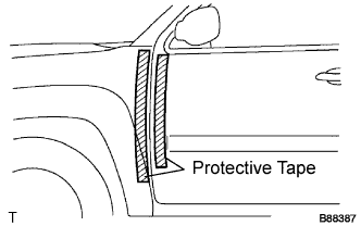 |
Apply strips of protective tape to the door panel and fender panel, as shown in the illustration.
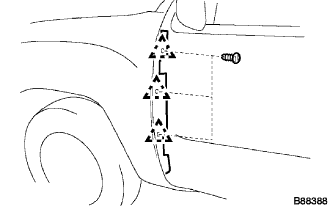 |
Open the door, and then disengage the 3 clips.
Remove the front fender side panel protector LH from the gap between the fender and door.
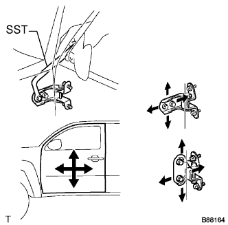 |
Using SST, adjust the door horizontally and vertically by loosening the body side hinge bolts.
Tighten the body side hinge bolts after the adjustment.
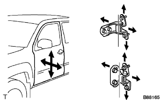 |
Horizontally and vertically adjust the door by loosening the door side hinge bolts.
Tighten the door side hinge bolts after the adjustment.
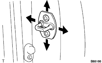 |
Adjust the striker position by slightly loosening the striker mounting screws with a torx socket wrench T40 and hitting the striker with a plastic hammer.
Using a torx socket wrench T40, tighten the striker mounting screws after the adjustment.
|
Install the front fender side panel protector LH with the 3 clips.
Connect the cable to the negative battery terminal.
Inspect the SRS warning lamp (Click here)