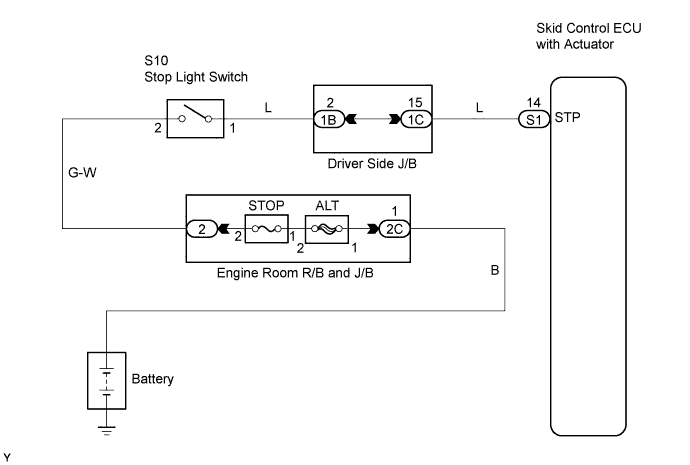
DTC C1249/49 Open in Stop Light Switch Circuit |
| DTC No. | DTC Detecting Condition | Trouble Areas |
| C1249/49 | ECU terminal IG1 voltage 9.5 V to 17.2 V and open in stop light switch circuit for 0.3 seconds or more. |
|
| 1.CHECK STOP LIGHT SWITCH OPERATION |
Check that the stop lights come on when the brake pedal is depressed and go off when the brake pedal is released.
| Pedal Condition | Illumination condition |
| Brake pedal depressed | ON |
| Brake pedal released | OFF |
|
| ||||
| OK | |
 |
| 2.INSPECT SKID CONTROL ECU TERMINAL VOLTAGE (STP TERMINAL) |
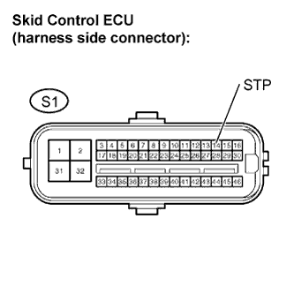 |
Disconnect the skid control ECU connector.
Measure the voltage.
| Tester Connection | Switch Condition | Specified Condition |
| S1-14 (STP) - Body ground | Brake pedal depressed | 8 to 16 V |
| S1-14 (STP) - Body ground | Brake pedal pressed | Below 1.5 V |
Reconnect the skid control ECU connector.
|
| ||||
| OK | |
|
| 3.RECONFIRM DTC |
Clear the DTCs (Click here).
Check if the same DTCs are detected.
| Result | Proceed to |
| DTC output | A |
| DTC not output | B |
|
| ||||
| A | ||
 | ||
| ||
| 4.INSPECT FUSE (STOP) |
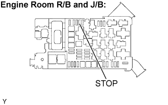 |
Remove the STOP fuse from the engine room R/B and J/B.
Measure the resistance of the STOP fuse.
Reinstall the STOP fuse.
|
| ||||
| OK | |
|
| 5.INSPECT STOP LIGHT SWITCH ASSEMBLY |
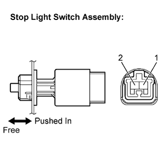 |
Disconnect the stop light switch connector.
Measure the resistance.
| Tester Connection | Switch Condition | Specified Condition |
| 1 - 2 | Switch pin free | Below 1 Ω |
| 1 - 2 | Switch pin pushed in | 10 kΩ or higher |
Reconnect the stop light switch connector.
|
| ||||
| OK | |
|
| 6.CHECK HARNESS AND CONNECTOR (STOP LIGHT SWITCH - SKID CONTROL ECU) |
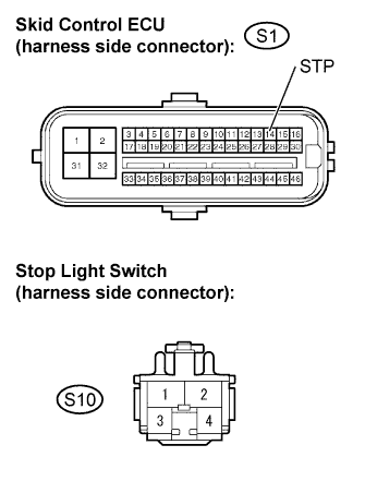 |
Disconnect the skid control ECU connector.
Disconnect the stop light switch connector.
Measure the resistance.
| Tester Connection | Specified Condition |
| S1-14 (STP) - S10-1 (STP) | Below 1 Ω |
Reconnect the stop light switch connector.
Reconnect the skid control ECU connector.
|
| ||||
| OK | |
|
| 7.RECONFIRM DTC |
Clear the DTCs (Click here).
Check if the same DTCs are detected.
| Result | Proceed to |
| DTC output | A |
| DTC not output | B |
|
| ||||
| A | ||
| ||
| ||

