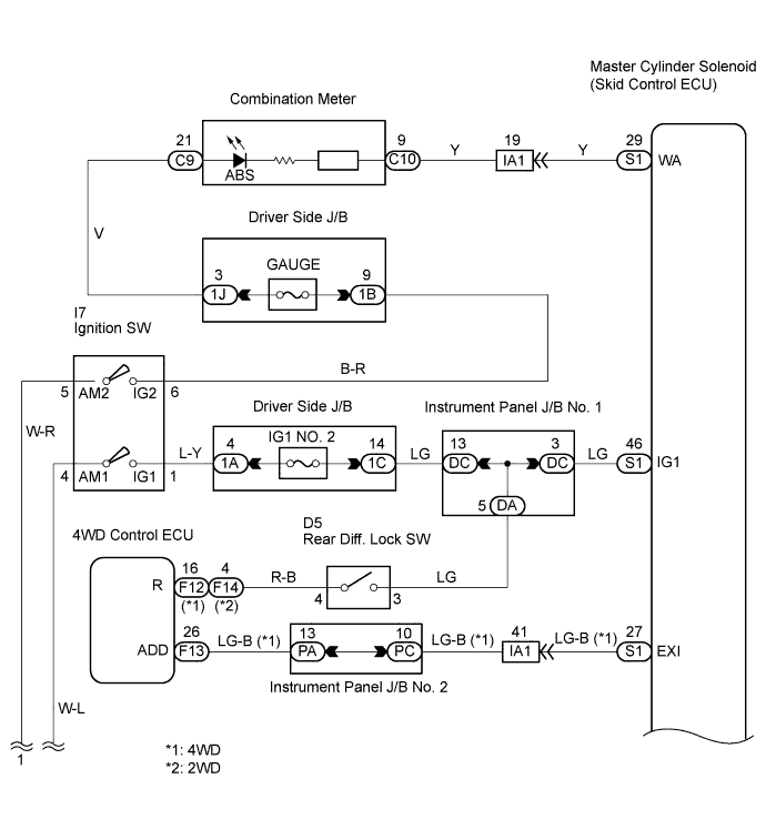
VEHICLE STABILITY CONTROL SYSTEM > ABS Warning Light Remains ON |
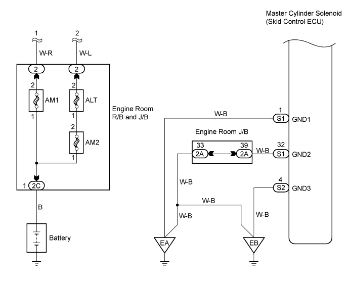
| 1.CHECK DTC |
Check if DTCs for ABS are recorded.
| Result | Proceed to |
| DTC not output | A |
| DTC output | B |
|
| ||||
| A | |
 |
| 2.INSPECT SKID CONTROL ECU CONNECTOR |
Check that the ECU connector is securely connected.
|
| ||||
| OK | |
|
| 3.INSPECT SKID CONTROL ECU (IG1 TERMINAL VOLTAGE) |
Connect the intelligent tester to the DLC3.
Start the engine.
Turn the intelligent tester ON.
Select the DATA LIST mode on the intelligent tester.
Measure the voltage output from the ECU displayed on the intelligent tester.
| Item | Measurement Item / Range (Display) | Normal Condition | Diagnostic Note |
| IG VOLTAGE | ECU power supply voltage / TOO LOW / NORMAL / TOO HIGH | TOO HIGH: 14 V or more NORMAL: 9.5 to 14V TOO LOW: Below 9.5 V | - |
|
| ||||
|
| ||||
| A | |
|
| 4.INSPECT REAR DIFFERENTIAL LOCK SWITCH |
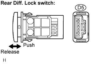 |
Remove the rear diff. lock switch.
Disconnect the rear diff. lock switch connector.
Measure the resistance.
| Tester Connection | Switch Condition | Specified Condition |
| D5-3 - D5-4 | Released | 10 kΩ or higher |
| D5-3 - D5-4 | Pushed in | Below 1 Ω |
Reinstall the rear diff. lock switch.
Reconnect the rear diff. lock switch connector.
|
| ||||
| OK | |
|
| 5.CHECK HARNESS AND CONNECTOR (4WD CONTROL ECU - REAR DIFFERENTIAL LOCK SWITCH) |
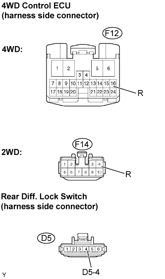 |
Disconnect the 4WD control ECU connector.
Disconnect the rear diff. lock connector.
Measure the resistance.
| Tester Connection | Specified Condition |
| F12-16 (R) - D5-4 | Below 1 Ω |
| F12-16 (R) - Body ground | 10 kΩ or higher |
| Tester Connection | Specified Condition |
| F14-4 (R) - D5-4 | Below 1 Ω |
| F14-4 (R) - Body ground | 10 kΩ or higher |
Reconnect the rear diff. lock connector.
Reconnect the 4WD control ECU connector.
|
| ||||
| OK | |
|
| 6.CHECK HARNESS AND CONNECTOR (SKID CONTROL ECU - COMBINATION METER) |
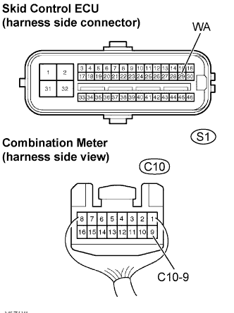 |
Disconnect the skid control ECU connector.
Disconnect the combination meter connector.
Measure the resistance.
| Tester Connection | Specified Condition |
| S1-29 (WA) - C10-9 | Below 1 Ω |
Measure the resistance.
| Tester Connection | Specified Condition |
| S1-29 (WA) - Body ground | 10 kΩ or higher |
Reconnect the combination meter connector.
Reconnect the skid control ECU connector.
|
| ||||
| OK | |
|
| 7.INSPECT COMBINATION METER ASSEMBLY |
Check the combination meter system (Click here).
|
| ||||
| OK | ||
 | ||
| ||

