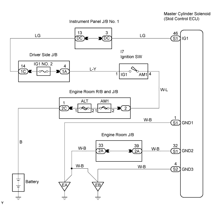
DTC C1241/41 Low Battery Positive Voltage |
| DTC No. | DTC Detecting Conditions | Trouble Areas |
| C1241/41 | When either of following conditions detected: 1. Both of following conditions continue for at least 10 seconds.
|
|
| 1.INSPECT BATTERY |
Check the battery voltage.
|
| ||||
| OK | |
 |
| 2.INSPECT FUSE (IG1 NO. 2) |
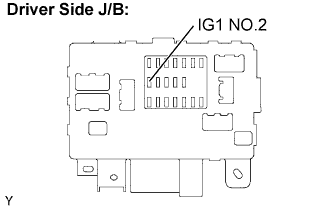 |
Remove the IG1 NO. 2 fuse from the driver side J/B.
Measure the resistance of the IG1 NO. 2 fuse.
Reinstall the IG1 NO. 2 fuse.
|
| ||||
| OK | |
|
| 3.READ VALUE OF DATA LIST (IG VOLTAGE) |
Connect the intelligent tester to the DLC3.
Turn the ignition switch to the ON position.
Turn the intelligent tester ON.
Select "DATA LIST" mode on the intelligent tester.
| Item | Measurement Item / Range (Display) | Normal Condition | Diagnostic Note |
| IG VOLTAGE | ECU power supply voltage / TOO LOW / NORMAL / TOO HIGH | TOO HIGH: 14 V or more NORMAL: 9.5 V or 14V TOO LOW: Below 9.5 V | - |
Measure the voltage output from the ECU displayed on the intelligent tester.
|
| ||||
| OK | |
|
| 4.INSPECT SKID CONTROL ECU (IG1 TERMINAL VOLTAGE) |
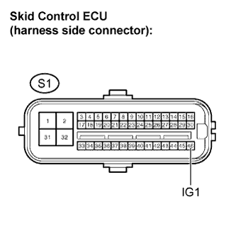 |
Disconnect the skid control ECU connector.
Turn the ignition switch to the ON position.
Measure the voltage.
| Tester Connection | Specified Condition |
| S1-46 (IG1) - Body ground | 10 to 14 V |
Turn the ignition switch to OFF.
Reconnect the skid control ECU connector.
|
| ||||
| OK | |
|
| 5.CHECK HARNESS AND CONNECTOR (GND TERMINAL CONTINUITY) |
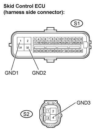 |
Disconnect the skid control ECU connectors.
Measure the resistance.
| Tester Connection | Specified Condition |
| S1-1 (GND1) - Body ground | Below 1 Ω |
| S1-32 (GND2) - Body ground | Below 1 Ω |
| S1-4 (GND3) - Body ground | Below 1 Ω |
Reconnect the skid control ECU connectors.
|
| ||||
| OK | |
|
| 6.RECONFIRM DTC |
Clear the DTCs (Click here).
Drive the vehicle at a speed of 1.9 mph (3 km/h) or more for 10 seconds or more.
Check if the same DTCs are detected.
| Result | Proceed to |
| DTC output | A |
| DTC not output (When troubleshooting in accordance with DTC CHART) | B |
| DTC not output (When troubleshooting in accordance with PROBLEM SYMPTOMS TABLE) | C |
|
| ||||
|
| ||||
| A | ||
 | ||
| ||
