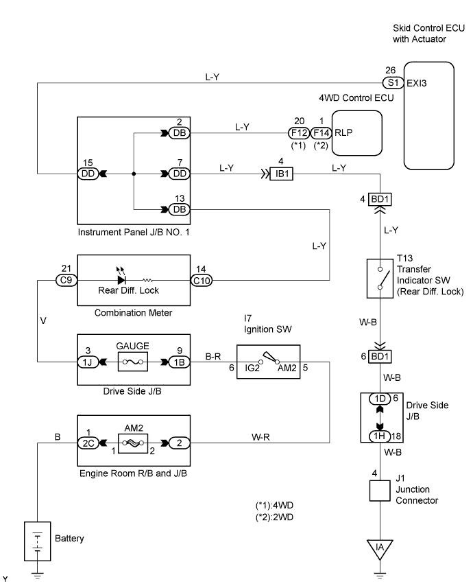
DTC C1248/48 Open Circuit in Rear Differential Lock |
| DTC No. | DTC Detecting Condition | Trouble Areas |
| C1248/48 | At vehicle speed of 31 mph (50 km/h) or more, 3 seconds or more elapse after rear differential changes from free to lock. |
|
| 1.INSPECT SKID CONTROL ECU (EXI3 TERMINAL VOLTAGE) |
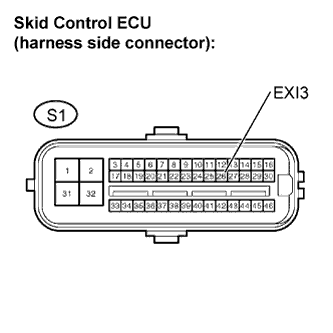 |
Disconnect the skid control ECU connector.
Turn the ignition switch to the ON position.
Measure the voltage.
| Tester Connection | Vehicle Condition | Specified Condition | Rear Diff. Lock Indicator Light |
| S1-26 (EXI3) - Body ground | Rear Differential free | 8 to 14 V | OFF |
| S1-26 (EXI3) - Body ground | Rear Differential locked | 1.5 V | ON |
Turn the ignition switch to OFF.
Reconnect the skid control ECU connector.
|
| ||||
| OK | |
 |
| 2.RECONFIRM DTC |
Clear the DTC (Click here).
Drive the vehicle at 31 mph (50 km/h) or more for 3 seconds or more with the rear differential free.
Check if the same DTCs are detected.
| Result | Proceed to |
| DTC output | A |
| DTC not output | B |
|
| ||||
| A | ||
 | ||
| ||
| 3.INSPECT TRANSFER INDICATOR SWITCH (REAR DIFF. LOCK) |
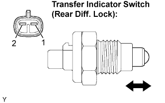 |
Disconnect the transfer indicator switch connector.
Remove the transfer indicator switch.
Measure the resistance.
| Tester Connection | Condition | Specified Condition |
| 1 - 2 | Pushed | Below 1 Ω |
| 1 - 2 | Free | 10 kΩ or higher |
Reinstall the transfer indicator switch.
Reconnect the transfer indicator switch connector.
|
| ||||
| OK | |
|
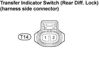
| 4.CHECK HARNESS AND CONNECTOR |
 |
Disconnect the skid control ECU connector.
Disconnect the 4WD control ECU connector.
Disconnect the transfer indicator switch connector.
Turn the ignition switch to the ON position.
Measure the voltage.
| Tester Connection | Specified Condition |
| T14-2 - Body ground | 8 to 14 V |
Turn the ignition switch to OFF.
Reconnect the transfer indicator switch connector.
Reconnect the 4WD control ECU connector.
Reconnect the skid control ECU connector.
|
| ||||
| NG | |
|
| 5.CHECK HARNESS AND CONNECTOR |
|
Disconnect the skid control ECU connector.
Disconnect the 4WD control ECU connector.
Disconnect the transfer indicator switch connector.
Disconnect the combination meter connector.
Measure the resistance.
| Tester Connection | Specified Condition |
| T14-2 - Body ground | 10 kΩ or higher |
Reconnect the combination meter connector.
Reconnect the transfer indicator switch connector.
Reconnect the 4WD control ECU connector.
Reconnect the skid control ECU connector.
|
| ||||
| OK | ||
| ||
| ||

