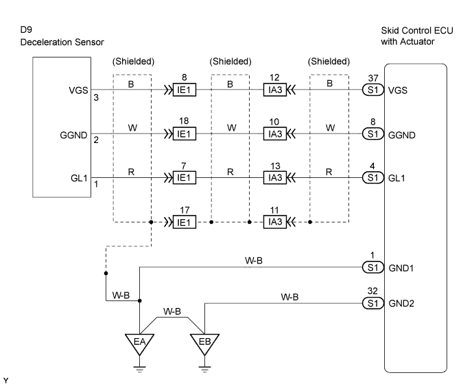
DTC C1243/43 Acceleration Sensor Stuck Malfunction |
DTC C1244/44 Open or Short in Deceleration Sensor Circuit |
DTC C1245/45 Acceleration Sensor Output Malfunction |
| DTC No. | DTC Detecting Conditions | Trouble Areas |
| C1243/43 | While vehicle speed decreases from 18 mph (30 km/h) to 0 mph (0 km/h), sensor signal does not change 16 times or more. |
|
| C1244/44 | When any of following 1 through 3 detected:
|
|
| C1245/45 | At vehicle speed of 18 mph (30 km/h) or more, difference between back and forth G value calculated using G sensor signals and back and forth G value calculated using vehicle speed, exceeds 0.35 G for 60 seconds or more. |
|
| 1.READ VALUE OF DATA LIST (DECELERATION SENSOR) |
Connect the intelligent tester to the DLC3.
Turn the ignition switch to the ON position.
Turn the intelligent tester ON.
Select the DATA LIST mode on the intelligent tester.
| Item | Measurement Item / Range (Display) | Normal Condition | Diagnostic Note |
| DECELERAT SEN | Deceleration sensor 1 reading / min.: -1.869 G, max.: 1.869 G | Approximately 0 +-0.13G in still condition | Reading changes when vehicle bounced |
Check that the deceleration value of the deceleration sensor displayed on the intelligent tester changes when the vehicle is tilted.
|
| ||||
| OK | |
 |
| 2.RECONFIRM DTC |
Clear the DTCs (Click here).
Check if the same DTCs are detected.
| Result | Proceed to |
| DTC output | A |
| DTC not output | B |
|
| ||||
| A | ||
 | ||
| ||
| 3.INSPECT DECELERATION SENSOR |
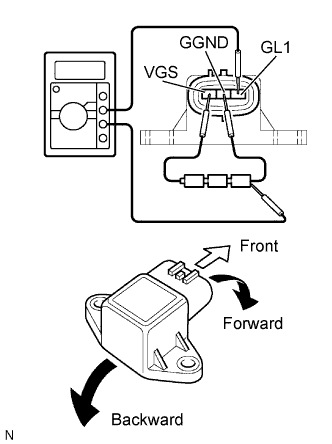 |
Remove the deceleration sensor.
Connect the 3 dry batteries of 1.5 V in series.
Connect the VGS terminal to the batteries' positive (+) terminal and the GGND terminal to the batteries' negative (-) terminal.
Apply about 4.5 V between the VGS and GGND terminals.
Check the output voltage of the GL1 terminal when the sensor is tilted forward and backward.
| Sensor Condition | Specified Condition |
| Horizontal | About 2.3 V |
| Lean forward | 0.4 to 2.3 V |
| Lean backward | 2.3 to 4.0 V |
|
| ||||
| OK | |
|
| 4.CHECK HARNESS AND CONNECTOR (SKID CONTROL ECU - DECELERATION SENSOR) |
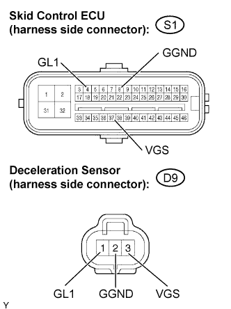 |
Disconnect the skid control ECU connector.
Disconnect the deceleration sensor connector.
Measure the resistance.
| Tester Connection | Specified Condition |
| S1-37 (VGS) - D9-3 (VGS) | Below 1 Ω |
| S1-8 (GGND) - D9-2 (GGND) | Below 1 Ω |
| S1-4 (GL1) - D9-1 (GL1) | Below 1 Ω |
Measure the resistance.
| Tester Connection | Specified Condition |
| S1-37 (VGS) - Body ground | 10 kΩ or higher |
| S1-8 (GGND) - Body ground | 10 kΩ or higher |
| S1-4 (GL1) - Body ground | 10 kΩ or higher |
Reconnect the deceleration sensor connector.
Reconnect the skid control ECU connector.
|
| ||||
| OK | ||
| ||
| ||

