TIRE PRESSURE WARNING ECU > INSTALLATION |
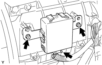
| 1. INSTALL TIRE PRESSURE WARNING ECU |
|
Install the tire pressure warning ECU with the 2 screws.
Connect the connector.
| 2. INSTALL INSTRUMENT LOWER COVER SUB-ASSEMBLY |
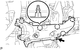 |
Connect the 2 connectors.
Engage the 5 clips and install the instrument lower cover.
Install the bolt <B>.
| 3. INSTALL LOWER INSTRUMENT PANEL LH |
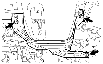 |
Install the lower instrument panel LH with the 3 bolts <B>.
| 4. INSTALL INSTRUMENT PANEL LOWER FINISH PANEL SUB-ASSEMBLY RH |
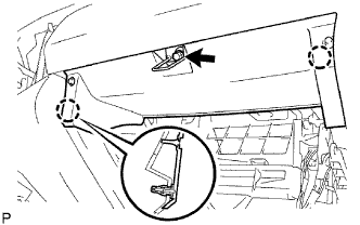 |
Engage the 2 clips and install the instrument panel lower finish panel sub-assembly RH.
Install the bolt <B>.
| 5. INSTALL GLOVE COMPARTMENT DOOR ASSEMBLY |
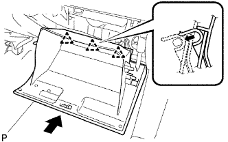 |
Install the glow compartment door assembly with 3 hinges, holding it horizontal.
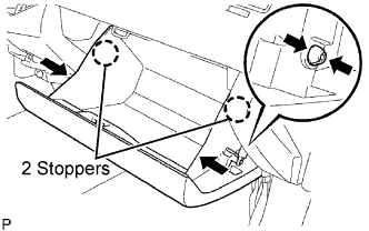 |
Slightly deform the upper part of the glove compartment door assembly, and install the glove compartment door assembly.
Install the glove compartment door stopper onto the glove compartment door.
| 6. INSTALL INSTRUMENT CLUSTER CENTER FINISH PANEL SUB-ASSEMBLY |
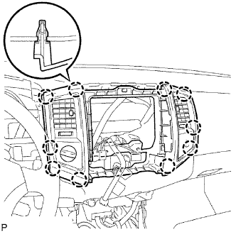 |
Engage the 10 clips and install the instrument cluster center finish panel sub-assembly.
| 7. INSTALL INSTRUMENT CLUSTER FINISH PANEL SUB-ASSEMBLY |
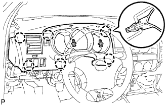 |
Connect the connectors.
Engage the 6 clips and install the instrument cluster finish panel sub-assembly.
Install the 2 clips.
| 8. INSTALL LOWER NO. 1 INSTRUMENT PANEL FINISH PANEL |
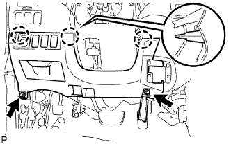 |
Connect the connectors.
Engage the 3 clips and install the lower NO. 1 instrument panel finish panel sub-assembly.
Install the 2 bolts <B>.
| 9. CONNECT HOOD LOCK CONTROL LEVER SUB-ASSEMBLY |
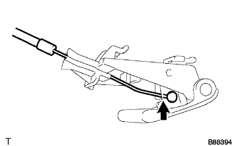 |
Connect the hood lock control cable assembly.
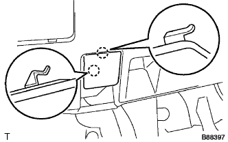 |
Engage the 2 claws and install the hood lock control lever sub-assembly.
| 10. INSTALL RADIO RECEIVER ASSEMBLY |
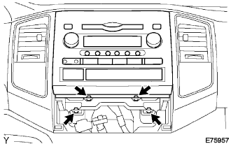 |
Connect the connector.
Install the radio receiver assembly with bracket with the 4 bolts.
| 11. INSTALL AIR CONDITIONING CONTROL ASSEMBLY |
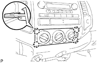 |
Connect the 2 connectors.
Engage the 4 clips and install the air conditioning control assembly.
| 12. INSTALL FRONT CONSOLE BOX (for Manual Transmission on Bench Seat Type) |
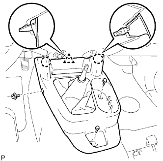 |
Engage the 2 clips and claw, and install the front console box.
Install the clip and 2 bolts <A>.
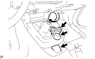 |
Install the No. 2 box bottom mat.
Install the instrument panel cup holder.
Install the box bottom mat.
Install the shift knob.
| 13. INSTALL FRONT CONSOLE BOX (for Automatic Transmission on Bench Seat Type) |
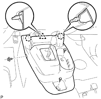 |
Engage the 2 clips and claw, and install the front console box.
Install the clip and 2 bolts <A>.
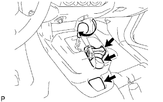 |
Install the No. 2 box bottom mat.
Install the instrument panel cup holder.
Install the box bottom mat.
Install the shift knob.
| 14. INSTALL FRONT CONSOLE BOX (for Manual Transmission on Separate Seat Type) |
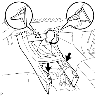 |
Engage the 2 clips and claw, and install the front console box.
Install the 2 screws <F>.
Install the shift knob.
| 15. INSTALL FRONT CONSOLE BOX (for Automatic Transmission on Separate Seat Type) |
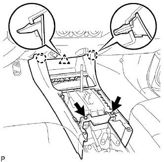 |
Engage the 2 clips and claw, and install the front console box.
Install the 2 screws <F>.
| 16. INSTALL INSTRUMENT PANEL CUP HOLDER TRAY (for Automatic Transmission on Separate Seat Type) |
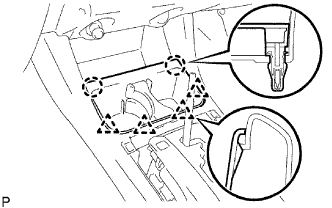 |
Engage the 2 clips and 4 claws, and install the instrument panel cup holder tray.
| 17. INSTALL REAR CONSOLE BOX ASSEMBLY (for Separate Seat Type) |
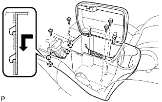 |
Engage the 4 claws and install the console box rear.
Install the 2 screws <F> and 2 bolts <B>.
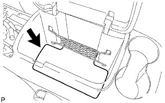 |
Install the console box carpet.
| 18. INSTALL CONSOLE UPPER REAR PANEL SUB-ASSEMBLY (for Manual Transmission on Separate Seat Type) |
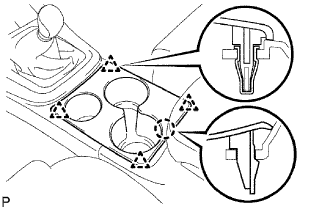 |
Engage the 4 clips and claw, and remove the console upper panel sub-assembly.
| 19. INSTALL CONSOLE UPPER REAR PANEL SUB-ASSEMBLY (for Automatic Transmission on Separate Seat Type) |
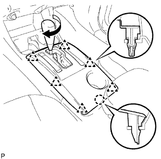 |
Engage the 6 clips and claw, and remove the console upper rear panel.
Install the shift knob.
| 20. INSTALL INSTRUMENT PANEL HOLE COVER (for Manual Transmission) |
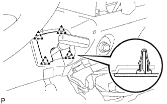 |
Engage the 4 clips and install the instrument panel hole cover.
| 21. INSTALL INSTRUMENT PANEL UNDER TRAY (for Automatic Transmission) |
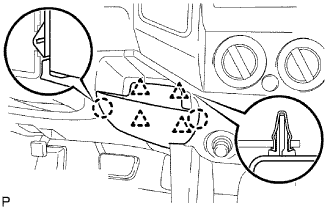 |
Engage the 4 clips and 2 claws, and install the instrument panel under tray.
| 22. INSTALL COWL SIDE TRIM BOARD LH (for Regular Cab) |
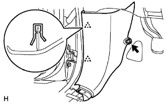 |
Engage the 2 clips and install the cowl side trim board.
Install the clip.
| 23. INSTALL COWL SIDE TRIM BOARD LH (for Access Cab) |
|
Engage the 2 clips and install the cowl side trim board.
Install the clip.
| 24. INSTALL COWL SIDE TRIM BOARD LH (for Double Cab) |
|
Engage the 2 clips and install the cowl side trim board.
Install the clip.
| 25. INSTALL FRONT DOOR SCUFF PLATE LH (for Regular Cab) |
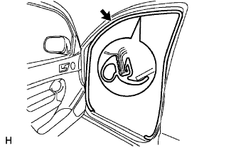 |
Install the front door opening trim weatherstrip.
| 26. INSTALL FRONT DOOR SCUFF PLATE LH (for Access Cab) |
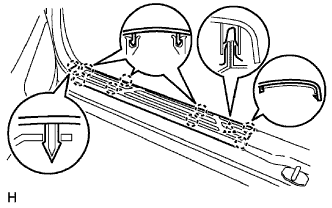 |
Engage the 9 claws and clip, and install the front door scuff plate.
| 27. INSTALL FRONT DOOR SCUFF PLATE LH (for Double Cab) |
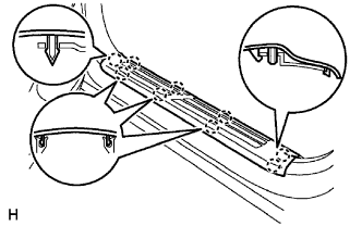 |
Engage the 9 claws and install the front door scuff plate.
| 28. INSTALL FRONT FLOOR FOOTREST |
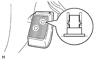 |
Engage the 2 clips and install the front floor footrest.
| 29. CONNECT CABLE TO NEGATIVE BATTERY TERMINAL |
| 30. REGISTER TRANSMITTER ID |
 |
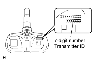 |
Prepare the all transmitter ID data before starting registration.
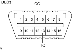
Connect the intelligent tester to the DLC3.
Turn the ignition switch to the ON position.
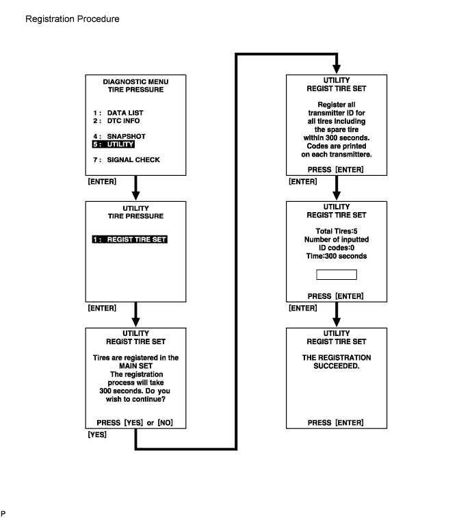
Select the REGIST TIRE by following the prompts displayed on the intelligent tester screen (UTILITY - REGIST TIRE).
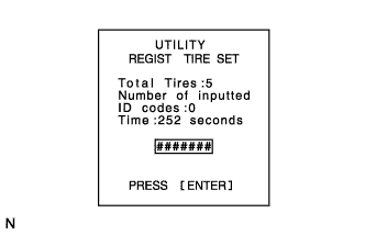 |
Input the IDs (ID1 to ID5) using the intelligent tester and transmit them to the tire pressure warning ECU.
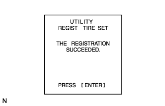 |
When the ID transmission has successfully been completed, the message shown in the illustration appears on the tester screen.
Turn the ignition switch to the OFF position, and then turn to the ON position.
Select "SIGNAL CHECK" on the intelligent tester (Click here ).
Confirm that the transmitter IDs and the data of tire pressure of all the tires are displayed on the intelligent tester screen.
| Item | Measurement Item/ Range (Display) | Normal Condition |
| REGIT ID1 CODE | Registered ID1 code/ minimum: 0 maximum: FFFFFFF | ID No. of registered transmitter ID1 displayed |
| REGIT ID2 CODE | Registered ID2 code/ minimum: 0 maximum: FFFFFFF | ID No. of registered transmitter ID2 displayed |
| REGIT ID3 CODE | Registered ID3 code/ minimum: 0 maximum: FFFFFFF | ID No. of registered transmitter ID3 displayed |
| REGIT ID4 CODE | Registered ID4 code/ minimum: 0 maximum: FFFFFFF | ID No. of registered transmitter ID4 displayed |
| REGIT ID5 CODE | Registered ID5 code/ minimum: 0 maximum: FFFFFFF | ID No. of registered transmitter ID5 displayed |
| TIREPRESS1 | ID1 tire pressure/ minimum: 0 kPa (0 kgf/cm2, 0 psi) maximum: 637.5 kPa (6.5 kgf/cm2, 92.5 psi) | Actual tire pressure |
| TIREPRESS2 | ID2 tire pressure/ minimum: 0 kPa (0 kgf/cm2, 0 psi) maximum: 637.5 kPa (6.5 kgf/cm2, 92.5 psi) | Actual tire pressure |
| TIREPRESS3 | ID3 tire pressure/ minimum: 0 kPa (0 kgf/cm2, 0 psi) maximum: 637.5 kPa (6.5 kgf/cm2, 92.5 psi) | Actual tire pressure |
| TIREPRESS4 | ID4 tire pressure/ minimum: 0 kPa (0 kgf/cm2, 0 psi) maximum: 637.5 kPa (6.5 kgf/cm2, 92.5 psi) | Actual tire pressure |
| TIREPRESS5 | ID5 tire pressure/ minimum: 0 kPa (0 kgf/cm2, 0 psi) maximum: 637.5 kPa (6.5 kgf/cm2, 92.5 psi) | Actual tire pressure |
Disconnect the intelligent tester with the ignition switch turned OFF.
| 31. INSPECT TIRE PRESSURE WARNING SYSTEM |