Home › SUSPENSION & AXLE › TIRE AND WHEEL › TIRE PRESSURE WARNING SYSTEM

TIRE PRESSURE WARNING SYSTEM > ECU Power Source Circuit

for Preparation Click here


DESCRIPTION

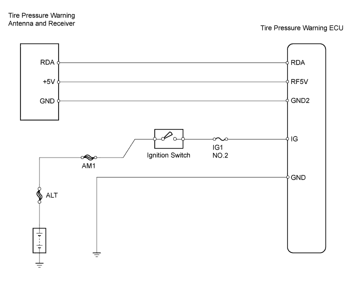
This circuit supplies power to the tire pressure warning ECU. The power is also supplied to the tire pressure warning antenna and receiver via the ECU.
The tire pressure warning system is disabled, when the system circuit has a defect. At This time the tire pressure warning light on the combination meter will come on.

WIRING DIAGRAM


C122907E01


INSPECTION PROCEDURE

NOTICE:
  1. When replacing the tire pressure warning ECU, read the IDs stored in the ECU using the intelligent tester and note them down before removal (Click here ).
  2. It is necessary to perform initialization (Click here) after registration (Click here ) the transmitter IDs into the tire pressure warning ECU after the ECU have been replaced.

1.INSPECT BATTERY
  1. Check the battery voltage.

    Standard voltage:
    11 to 14 V


NG
CHECK AND REPAIR CHARGING SYSTEM
OK


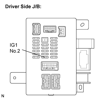
2.INSPECT FUSE (IG1 No.2)


    C122896E01
  1. Remove the IG1 No.2 fuse from the driver side J/B.

  1. Measure the resistance of the IG1 No.2 fuse.

    Standard resistance:
    Below 1 Ω

  1. Reinstall the IG1 No.2 fuse.


NG
CHECK SHORT CIRCUIT IN COMPONENTS AND WIRES CONNECTED TO FUSE
OK


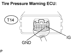
3.INSPECT TIRE PRESSURE WARNING ECU


    C117152E10
  1. Remove the tire pressure warning ECU with the connector connected.

  1. Turn the ignition switch to the ON position.

  1. Measure the voltage.

    Standard voltage:
    Tester Connection
    Specified Condition
    IG (T14-2) - GND (T14-11)
    10 to 16 V


NG
Go to step 4
OK

PROCEED TO NEXT CIRCUIT INSPECTION SHOWN IN PROBLEM SYMPTOMS TABLE 

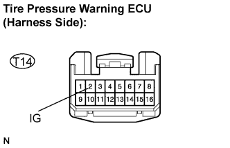
4.CHECK HARNESS AND CONNECTOR (BATTERY - TIRE PRESSURE WARNING ECU)


    C122898E06
  1. Disconnect the connector from the tire pressure warning ECU.

  1. Turn the ignition switch to the ON position.

  1. Measure the voltage.

    Standard voltage:
    Tester Connection
    Specified Condition
    IG (T14-2) - Body ground
    10 to 16 V

  1. Reconnect the connector.


NG
REPAIR OR REPLACE HARNESS OR CONNECTOR
OK


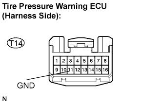
5.CHECK HARNESS AND CONNECTOR (TIRE PRESSURE WARNING ECU - BODY GROUND)


    C122898E07
  1. Disconnect the connector from the tire pressure warning ECU.

  1. Measure the resistance.

    Standard resistance:
    Tester connection
    Specified Condition
    GND (T14-11) - Body ground
    Below 1 Ω


NG
REPAIR OR REPLACE HARNESS OR CONNECTOR
OK

PROCEED TO NEXT CIRCUIT INSPECTION SHOWN IN PROBLEM SYMPTOMS TABLE