Home › SUSPENSION & AXLE › TIRE AND WHEEL › TIRE PRESSURE WARNING SYSTEM

DTC    C2141/41    Transmitter ID1 Error

DTC    C2142/42    Transmitter ID2 Error

DTC    C2143/43    Transmitter ID3 Error

DTC    C2144/44    Transmitter ID4 Error

DTC    C2145/45    Transmitter ID5 Error

for Preparation Click here


DESCRIPTION

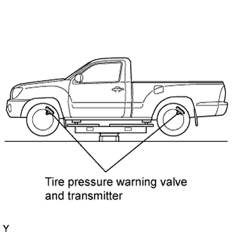
Tire pressure warning valve and transmitters that are installed in the tire and wheel assemblies measure the air pressures of the tires. The measured values are transmitted to the tire pressure warning antenna and receiver on the body as radio waves and then sent to the tire pressure warning ECU. The ECU compares the measured air pressure values with the air pressure threshold. When the measured air pressure values are less than this threshold, the warning light in the combination meter comes on.
When the internal circuits of the tire pressure warning valve and transmitters are defected, these DTCs are output.

DTC No.
DTC Detection Condition
Trouble Area
C2141/41
C2142/42
C2143/43
C2144/44
C2145/45
  1. If ERROR signal received 3 times consecutively, tire pressure warning valve and transmitter determined to be defective.
  2. This occurs in situations where tire pressure outside range 0 to 637.5 kPa (0 to 6.5 kgf / cm2, 0 to 92.5 psi), tire internal temperature outside specified range - 40 to 120°C (- 40 to 248°F), or error occurs in tire pressure warning valve and transmitter
  1. Tire pressure warning valve and transmitter

INSPECTION PROCEDURE

NOTICE:
  1. When replacing the tire pressure warning ECU, read the IDs stored in the ECU using the intelligent tester and note them down before removal (Click here ).
  2. It is necessary to perform initialization (Click here) after registration (Click here ) the transmitter IDs into the tire pressure warning ECU after the tire pressure warning ECU and/or tire pressure warning valve and transmitter have been replaced.

1.IDENTIFY TRANSMITTER (CORRESPONDING TO DTC)
  1. Set the tire pressures to the appropriate specified values.

    Tire Size
    Front Wheel
    kPa (kgf/cm2, psi)
    Rear Wheel
    kPa (kgf/cm2, psi)
    Spare Wheel
    kPa (kgf/cm2, psi)
    P215/70 R15
    200 (2.0, 29)
    220 (2.2, 32)
    220 (2.2, 32)
    P255/45 R18
    240 (2.4, 34)
    240 (2.4, 34)
    240 (2.4, 34)
    P245/75 R16
    200 (2.0, 29)
    200 (2.0, 29)
    200 (2.0, 29)
    P265/70 R16 (ORP)*
    200 (2.0, 29)
    220 (2.2, 32)
    220 (2.2, 32)
    P265/65 R17
    200 (2.0, 29)
    200 (2.0, 29)
    200 (2.0, 29)
    *: Used on Off Road Package Models


    C124984E01
  1. Jack up the vehicle.

  1. Select TIREPRESS by following the prompts displayed on the intelligent tester.
    Item
    Measurement Item / Range (Display)
    TIREPRESS1
    ID1 tire inflation pressure/
    minimum: 0 kPa (0 kgf/cm2, 0 psi)
    maximum: 637.5 kPa (6.5 kgf/cm2, 92.5 psi)
    TIREPRESS2
    ID2 tire inflation pressure/
    minimum: 0 kPa (0 kgf/cm2, 0 psi)
    maximum: 637.5 kPa (6.5 kgf/cm2, 92.5 psi)
    TIREPRESS3
    ID3 tire inflation pressure/
    minimum: 0 kPa (0 kgf/cm2, 0 psi)
    maximum: 637.5 kPa (6.5 kgf/cm2, 92.5 psi)
    TIREPRESS4
    ID4 tire inflation pressure/
    minimum: 0 kPa (0 kgf/cm2, 0 psi)
    maximum: 637.5 kPa (6.5 kgf/cm2, 92.5 psi)
    TIREPRESS5
    ID5 tire inflation pressure/
    minimum: 0 kPa (0 kgf/cm2, 0 psi)
    maximum: 637.5 kPa (6.5 kgf/cm2, 92.5 psi)

    NOTICE:
    It may take up to 1 minute to display the updated data.

  1. Rapidly release the tire pressure from any tire to 40 kPa (0.4 kgf/cm2, 5.8 psi).

    HINT:
    1. Identify the malfunctioning tire pressure warning valve and transmitter by rapidly releasing the tire pressures from each tire.
    2. Record which TIREPRESS data (ID1 to ID5) corresponds to each tire.

  1. Check the DATA LIST.

    Result:
    Display
    Detection Condition
    One of TIREPRESS data (ID1 to ID5) changes
    Normal
    None of TIREPRESS data change
    Transmitter corresponding to DTC

    NOTICE:
    1. When none of the TIREPRESS data (IDs 1 to 5) change, reset the tire pressure to the appropriate specified values and rotate the tires 90 to 270 degrees and recheck.
    2. When the transmitter is normal, record the tire location and the transmitter ID.

  1. When one of the TIREPRESS data (IDs 1 to 5) changes, repeat the same procedure on the rest of tires one by one to identify which tire pressure warning valve and transmitter the DTC corresponds to.

  1. When all the TIREPRESS data (IDs 1 to 5) has been changed, identify the malfunctioning tire pressure warning valve and transmitter by using recorded ID numbers and output DTC.

  1. Set the tire pressures to the appropriate specified values.


NEXT

REPLACE TIRE PRESSURE WARNING VALVE AND TRANSMITTER