w/ Vanity Light:
Install the roof wire with 20 new adhesive tapes, as shown in the illustration.
Connect the 2 roof speaker connectors.
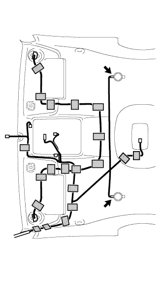 |
ROOF HEADLINING (for Access Cab) > INSTALLATION |
| 1. INSTALL ROOF WIRE |
w/ Vanity Light:
|
Install the roof wire with 20 new adhesive tapes, as shown in the illustration.
Connect the 2 roof speaker connectors.
w/o Vanity Light:
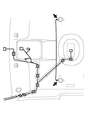 |
Install the roof wire with 9 new adhesive tapes, as shown in the illustration.
Connect the 2 roof speaker connectors.
| 2. INSTALL ROOF HEADLINING PAD |
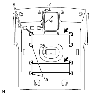 |
Install the 2 new roof headlining pads onto the roof headlining, as shown in the illustration.
| *a | Grooves |
| 3. INSTALL ROOF HEADLINING ASSEMBLY |
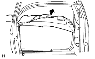 |
Install the roof headlining into the vehicle.
Install the wire harness clamps.
Connect the 3 roof wire connectors.
| 4. INSTALL COAT HOOK |
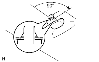 |
Turn the coat hook 90° clockwise and install it.
| 5. INSTALL VISOR HOLDER |
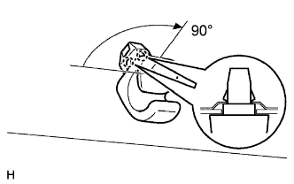 |
Turn the visor holder 90° clockwise and install it.
| 6. INSTALL VISOR ASSEMBLY LH |
Install the visor into the visor holder.
Tighten the 2 screws.
| 7. INSTALL VISOR ASSEMBLY RH |
| 8. INSTALL ASSIST GRIP PLUG |
Engage the claw and install the assist grip plug.
Tighten the screw.
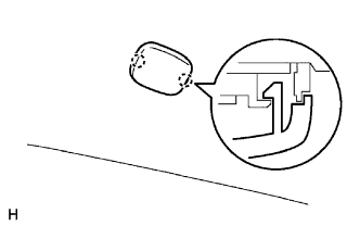 |
Engage the 2 claws and close the cover.
| 9. INSTALL ROOF CONSOLE BOX ASSEMBLY |
Install the wire harness clamp.
Connect the accessory meter connector and map lamp connector.
Engage the 2 clips and 3 claws and install the map lamp.
Tighten the screw.
| 10. INSTALL ROOM LIGHT ASSEMBLY |
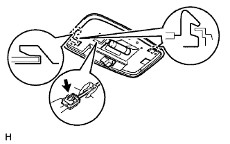 |
Connect the room light connector.
Engage the 3 claws and install the room light.
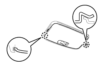 |
Engage the 2 claws and install the room light lens.
| 11. INSTALL QUARTER INSIDE TRIM BOARD LH |
Engage the 3 clips and install the quarter inside trim board.
Tighten the screw.
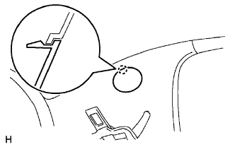 |
Engage the claw and close the cover.
| 12. INSTALL QUARTER INSIDE TRIM BOARD RH |
| 13. INSTALL ROOF SIDE INNER GARNISH LH |
Engage the 2 claws and clip, and install the roof side inner garnish.
| 14. INSTALL ROOF SIDE INNER GARNISH RH |
| 15. INSTALL QUARTER TRIM LOWER PANEL LH |
Engage the claw and 2 clips, and install the quarter trim lower panel.
Install the floor anchor of the rear seat belt outer with the bolt.
| 16. INSTALL QUARTER TRIM LOWER PANEL RH |
| 17. INSTALL BACK PANEL TRIM |
Engage the 8 claws and 14 clips, and install the back panel trim.
Install the 2 clips.
| 18. INSTALL BACK PANEL TRIM COVER |
Engage the 4 claws and install the back panel trim cover.
| 19. INSTALL BACK PANEL GARNISH HOLE PLUG |
Engage the 4 claws and install the 2 back panel garnish hole plugs.
| 20. INSTALL REAR SEAT CUSHION ASSEMBLY |
| 21. INSTALL NO. 1 SPEAKER ASSEMBLY WITH BOX |
| 22. INSTALL INSTRUMENT PANEL SUB-ASSEMBLY |
Install the instrument panel sub-assembly with passenger airbag assembly with the 8 bolts and nut.
Engage the 5 clamps and connect the 4 connectors.
Remove the protective tape from the steering column cover upper and steering wheel sub-assembly.
| 23. CONNECT PASSENGER AIRBAG CONNECTOR |
| 24. INSTALL INSTRUMENT SIDE PANEL |
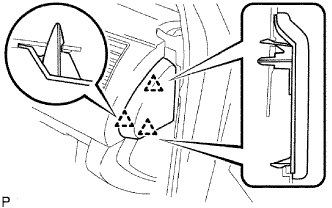 |
Engage the 3 claws and install the instrument side RH.
| 25. INSTALL INSTRUMENT LOWER COVER SUB-ASSEMBLY |
Connect the connectors.
Engage the 5 clips and install the instrument lower cover.
Install the bolt <B>.
| 26. INSTALL INSTRUMENT LOWER PANEL |
Install the lower instrument panel LH with the 3 bolts <B>.
| 27. INSTALL INSTRUMENT LOWER PANEL FINISH PANEL SUB-ASSEMBLY |
Engage the 2 clips and install the instrument panel lower finish panel sub-assembly RH.
Install the bolt <B>.
| 28. INSTALL GLOVE COMPARTMENT DOOR ASSEMBLY |
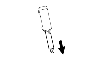 |
Pull the bottom of the stopper.
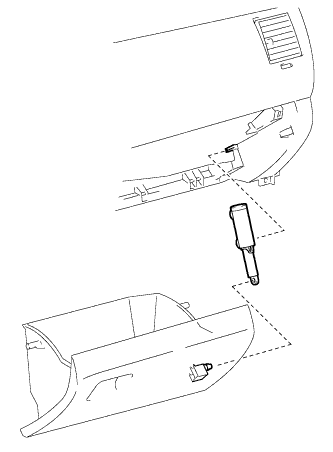 |
Attach the stopper to the glove compartment door as shown in the illustration.
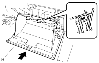 |
Install the glove compartment door assembly with 3 hinges, holding it horizontal.
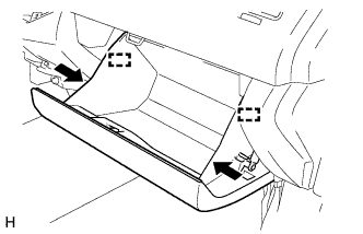 |
Slightly deform the upper part of the glove compartment door assembly, and install the glove compartment door assembly.
| 29. INSTALL INSTRUMENT CENTER CLUSTER FINISH PANEL SUB-ASSEMBLY |
Engage the 10 clips and install the instrument cluster center finish panel sub-assembly.
| 30. INSTALL COMBINATION METER ASSEMBLY |
Connect the 2 connectors.
Install the combination meter assembly with the 4 screws <E>.
| 31. INSTALL INSTRUMENT CLUSTER FINISH PANEL SUB-ASSEMBLY |
Connect the connectors.
Engage the 6 clips and install the instrument cluster finish panel sub-assembly.
Install the 2 clips.
| 32. INSTALL INSTRUMENT LOWER PANEL FINISH PANEL |
Connect the connectors.
Engage the 3 clips and install the lower NO. 1 instrument panel finish panel sub-assembly.
Install the 2 bolts <B>.
| 33. CONNECT HOOD LOCK CONTROL LEVER SUB-ASSEMBLY |
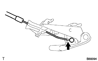 |
Connect the hood lock control cable assembly.
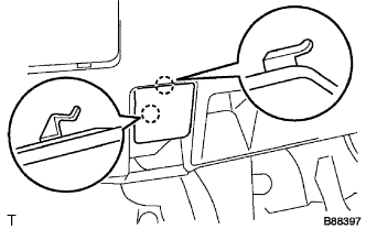 |
Engage the 2 claws and install the hood lock control lever sub-assembly.
| 34. INSTALL RADIO RECEIVER ASSEMBLY WITH BRACKET |
Connect all the connectors.
Connect the plug.
Engage the 5 clips and install the radio receiver assembly with bracket.
Install the 4 bolts.
| 35. INSTALL AIR CONDITIONING CONTROL ASSEMBLY |
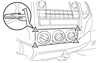 |
Connect the 2 connectors.
Engage the 4 clips and install the air conditioning control assembly.
| 36. INSTALL FRONT CONSOLE BOX |
for Automatic Transmission:
Install the front console box .
for Manual Transmission:
Install the front console box .
| 37. INSTALL INSTRUMENT PANEL CUP HOLDER TRAY (for Automatic Transmission) |
Engage the 2 clips and 4 claws, and install the instrument panel cup holder tray.
Install the 2 instrument panel cup holders.
| 38. INSTALL REAR CONSOLE BOX ASSEMBLY |
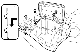 |
Engage the 4 claws and install the console box rear.
Install the 2 screws <F> and 2 bolts <B>.
Install the console box carpet.
| 39. INSTALL REAR CONSOLE UPPER PANEL SUB-ASSEMBLY |
for Automatic Transmission:
Install the rear console upper panel sub-assembly .
for Manual Transmission:
Install the rear console upper panel sub-assembly .
| 40. INSTALL INSTRUMENT PANEL UNDER TRAY (for Pedal Type Parking Brake) |
Engage the 4 clips and 2 claws, and install the instrument panel under tray.
| 41. INSTALL INSTRUMENT PANEL HOLE COVER (for Lever Type Parking Brake) |
Engage the 4 clips and install the instrument panel hole cover.
| 42. INSTALL FRONT PILLAR GARNISH LH |
for LH Side:
Install the 3 wire harness clamps.
Engage the claw and clip, and install the front pillar garnish and assist grip.
Tighten the 2 screws.
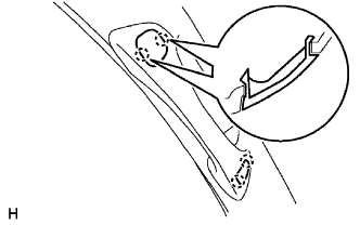 |
Engage the 2 claws and install the assist grip plug.
| 43. INSTALL FRONT PILLAR GARNISH RH |
| 44. INSTALL FRONT DOOR OPENING TRIM WEATHERSTRIP LH |
Install the front door opening trim weatherstrip.
| 45. INSTALL FRONT DOOR OPENING TRIM WEATHERSTRIP RH |
| 46. INSTALL ROOF SIDE INNER GARNISH CAP LH |
Engage the 4 claws and install the roof side inner garnish cap.
Using a "TORX" socket wrench T30, tighten the 2 screws.
| 47. INSTALL ROOF SIDE INNER GARNISH CAP RH |
| 48. INSTALL ROOF SIDE INNER GARNISH COVER LH |
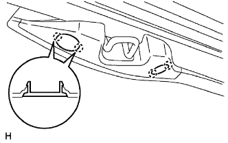 |
Engage the 2 claws and install the roof side inner garnish cover.
| 49. INSTALL ROOF SIDE INNER GARNISH COVER RH |
| 50. INSTALL REAR DOOR SCUFF PLATE LH |
Engage the 7 claws and install the rear door scuff plate.
| 51. INSTALL REAR DOOR SCUFF PLATE RH |
| 52. INSTALL COWL SIDE TRIM BOARD LH |
Engage the 2 clips and install the cowl side trim board.
Install the clip.
| 53. INSTALL COWL SIDE TRIM BOARD RH |
| 54. INSTALL FRONT DOOR SCUFF PLATE LH |
Engage the 9 claws and clip, and install the front door scuff plate.
| 55. INSTALL FRONT DOOR SCUFF PLATE RH |
| 56. INSTALL FRONT FLOOR FOOTREST |
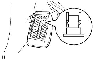 |
Engage the 2 clips and install the front floor footrest.
| 57. INSTALL INNER REAR VIEW MIRROR COVER (w/ EC Mirror) |
Connect the connector.
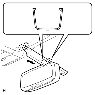 |
Engage the 2 claws of the inner rear view mirror cover to the mirror, and then slide the inner rear view mirror cover in the direction indicated by the arrow in the illustration to engage the 2 claws to the roof headlining and install the inner rear view mirror cover.
| 58. CONNECT CABLE TO NEGATIVE BATTERY TERMINAL |
| 59. INSPECT SRS WARNING LIGHT |