Home › BODY › INTERIOR › ROOF HEADLINING (for Access Cab)

ROOF HEADLINING (for Access Cab) > REMOVAL

for Preparation Click here


1. PRECAUTION

NOTICE:
After turning the ignition switch off, waiting time may be required before disconnecting the cable from the battery terminal. Therefore, make sure to read the disconnecting the cable from the battery terminal notice before proceeding with work (Click here).


2. DISCONNECT CABLE FROM NEGATIVE BATTERY TERMINAL

CAUTION:
Wait at least 90 seconds after disconnecting the cable from the negative (-) battery terminal to disable the SRS system.


3. REMOVE INNER REAR VIEW MIRROR COVER (w/ EC Mirror)


    B227021
  1. Slide the inner rear view mirror cover in the direction indicated by the arrow in the illustration to disengage the 2 claws from the roof headlining, and then disengage the 2 claws of the inner rear view mirror cover from the mirror and remove the inner rear view mirror cover.
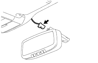
    E232406
  1. Disconnect the connector.


4. REMOVE FRONT FLOOR FOOTREST


    B087437E01
  1. Disengage the 2 clips and remove the front floor footrest.


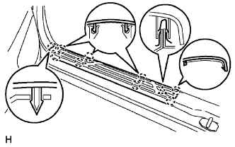
5. REMOVE FRONT DOOR SCUFF PLATE LH


    B087436E01
  1. Disengage the 9 claws and clip, and remove the front door scuff plate.


6. REMOVE FRONT DOOR SCUFF PLATE RH

HINT:
Follow the same procedures as for the front door scuff plate LH.


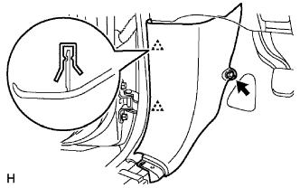
7. REMOVE COWL SIDE TRIM BOARD LH


    B087438E01
  1. Remove the clip.

  1. Disengage the 2 clips and remove the cowl side trim board.


8. REMOVE COWL SIDE TRIM BOARD RH

HINT:
Follow the same procedures as for the cowl side trim board LH.


9. REMOVE REAR DOOR SCUFF PLATE LH


    B087439E01
  1. Disengage the 7 claws and remove the rear door scuff plate.


10. REMOVE REAR DOOR SCUFF PLATE RH

HINT:
Follow the same procedures as for the rear door scuff plate LH.


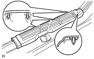
11. REMOVE ROOF SIDE INNER GARNISH COVER LH

HINT:
Follow the same procedures as for the opposite side.


    B087440E03
  1. Using a screwdriver with its tip taped in protective tape, disengage the 2 claws and remove the roof side inner garnish cover.
    Text in Illustration 
    *1
    Protective Tape


12. REMOVE ROOF SIDE INNER GARNISH COVER RH

HINT:
Follow the same procedures as for the roof side inner garnish cover LH.


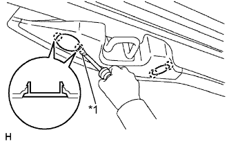
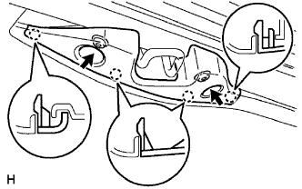
13. REMOVE ROOF SIDE INNER GARNISH CAP LH


    B087441E01
  1. Using a "TORX" socket wrench T30, remove the 2 screws.

  1. Disengage the 4 claws and remove the roof side inner garnish cap.


14. REMOVE ROOF SIDE INNER GARNISH CAP RH

HINT:
Follow the same procedures as for the roof side inner garnish cap LH.


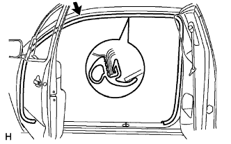
15. REMOVE FRONT DOOR OPENING TRIM WEATHERSTRIP LH


    B087442E01
  1. Remove the front door opening trim weatherstrip.


16. REMOVE FRONT DOOR OPENING TRIM WEATHERSTRIP RH

HINT:
Follow the same procedures as for the front door opening trim weatherstrip LH.


17. REMOVE FRONT PILLAR GARNISH LH


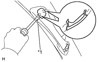
    B087443E04
  1. Using a screwdriver with its tip taped in protective tape, disengage the 2 claws and remove the assist grip plug.
    Text in Illustration 
    *1
    Protective Tape

    HINT:
    Follow the same procedures as for the opposite side.


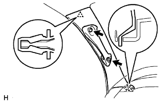
    B087444E01
  1. Remove the 2 screws.

  1. Disengage the claw and clip, and remove the front pillar garnish.


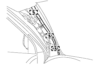
    B290414
  1. for LH Side:

    1. Using a clip remover, remove the 3 wire harness clamps.


18. REMOVE FRONT PILLAR GARNISH RH

HINT:
Follow the same procedures as for the front pillar garnish LH.


19. REMOVE INSTRUMENT PANEL UNDER TRAY (for Pedal Type Parking Brake)


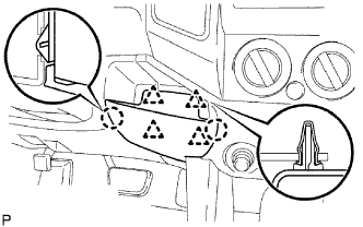
    B085766E01
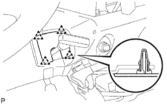
  1. Disengage the 4 clips and 2 claws, and remove the instrument panel under tray.


20. REMOVE INSTRUMENT PANEL HOLE COVER (for Lever Type Parking Brake)


    B085767E01
  1. Disengage the 4 clips and remove the instrument panel hole cover.


21. REMOVE REAR CONSOLE UPPER PANEL SUB-ASSEMBLY
  1. for Automatic Transmission:

    1. Remove the rear console upper panel sub-assembly .

  1. for Manual Transmission:

    1. Remove the rear console upper panel sub-assembly .


22. REMOVE REAR CONSOLE BOX ASSEMBLY


    B290398
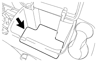
  1. Remove the console box carpet.


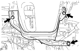
    B290399
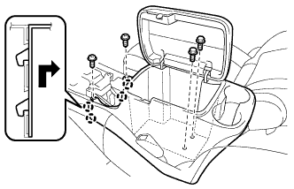
  1. Remove the 2 screws <F> and 2 bolts <B>.

  1. Disengage the 4 claws and remove the rear console box assembly.


23. REMOVE INSTRUMENT PANEL CUP HOLDER TRAY (for Automatic Transmission)


    B290400
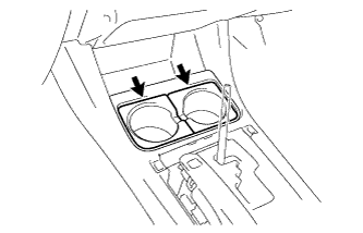
  1. Remove the 2 instrument panel cup holders.


    B290401
  1. Disengage the 2 clips and 4 claws, and remove the instrument panel cup holder tray.


24. REMOVE FRONT CONSOLE BOX
  1. for Automatic Transmission:

    1. Remove the front console box .

  1. for Manual Transmission:

    1. Remove the front console box .


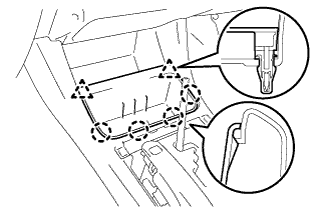
25. REMOVE AIR CONDITIONING CONTROL ASSEMBLY


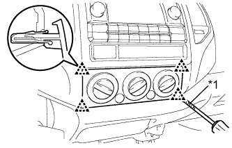
    E212043E01
  1. Using a screwdriver with its tip wrapped in protective tape, disengage the 4 clips and remove the air conditioner control assembly.
    Text in Illustration 
    *1
    Protective Tape

  1. Disconnect the 2 connectors.


26. REMOVE RADIO RECEIVER ASSEMBLY WITH BRACKET


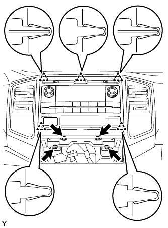
    E232403
  1. Remove the 4 bolts.

  1. Disengage the 5 clips and remove the radio receiver assembly with bracket.

    NOTICE:
    Be careful not to damage the clips.

  1. Disconnect the plug.

  1. Disconnect all the connectors.


27. SEPARATE HOOD LOCK CONTROL LEVER SUB-ASSEMBLY


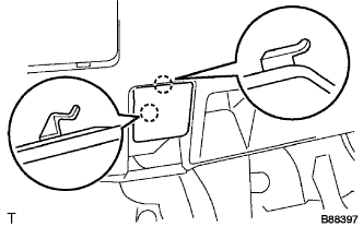
    B088397E01
  1. Disengage the 2 claws.


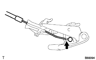
    B088394
  1. Disconnect the hood lock control cable assembly and remove the hood lock control lever sub-assembly.


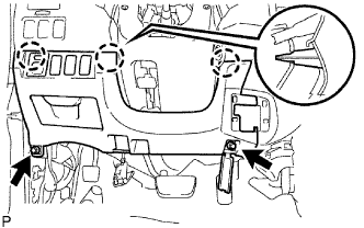
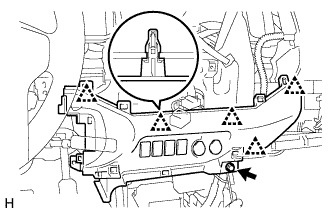
28. REMOVE INSTRUMENT LOWER PANEL FINISH PANEL


    B085780E01
  1. Remove the 2 bolts <B>.

  1. Disengage the 3 clips and remove the lower No. 1 instrument panel finish panel.

  1. Disconnect the connectors.


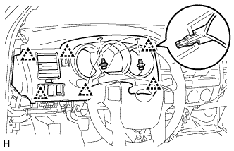
29. REMOVE INSTRUMENT CLUSTER FINISH PANEL SUB-ASSEMBLY


    E232348
  1. Remove the 2 clips.

  1. Disengage the 6 clips and remove the instrument cluster finish panel sub-assembly.

  1. Disconnect the connectors.


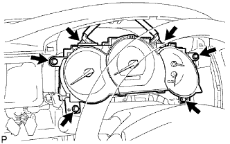
30. REMOVE COMBINATION METER ASSEMBLY


    B085782E01
  1. Remove the 4 screws <E> and the combination meter assembly.

  1. Disconnect the 2 connectors.


31. REMOVE INSTRUMENT CENTER CLUSTER FINISH PANEL SUB-ASSEMBLY


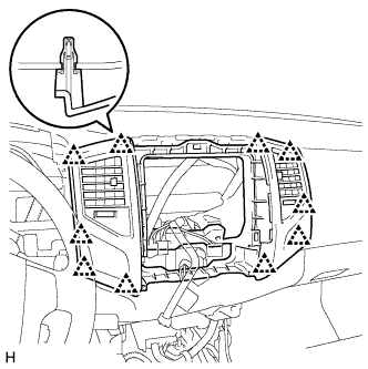
    E232349
  1. Disengage the 10 clips and remove the instrument cluster center finish panel sub-assembly.


32. REMOVE GLOVE COMPARTMENT DOOR ASSEMBLY


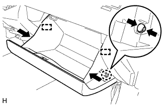
    E232350
  1. Disengage the claw and separate the glove compartment door stopper from the glove compartment door assembly.

  1. Slightly deform the upper part of the glove compartment door assembly to release the 2 stoppers and open the glove compartment door assembly until it becomes horizontal.


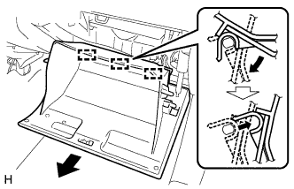
    E232351
  1. Pull the glove compartment door assembly toward the rear of the vehicle to release the 3 hinges and remove the glove compartment door assembly.

  1. Remove the glove compartment door stopper.


33. REMOVE INSTRUMENT LOWER PANEL FINISH PANEL SUB-ASSEMBLY


    E232352
  1. Remove the bolt <B>.

  1. Disengage the 2 clips and remove the instrument panel lower finish panel sub-assembly RH.


34. REMOVE INSTRUMENT LOWER PANEL


    B085788E01
  1. Remove the 3 bolts <B> and the lower instrument panel LH.


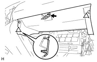
35. REMOVE INSTRUMENT LOWER COVER SUB-ASSEMBLY


    E232353
  1. Remove the bolt <B>.

  1. Disengage the 5 clips and remove the instrument lower cover sub-assembly.

  1. Disconnect the connectors.


36. REMOVE INSTRUMENT SIDE PANEL


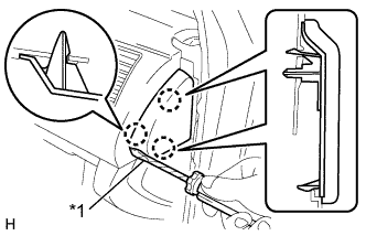
    E232354E01
  1. Using a screwdriver, disengage the 3 claws and remove the instrument side panel RH.
    Text in Illustration 
    *1
    Protective Tape

    HINT:
    Tape the screwdriver tip before use.


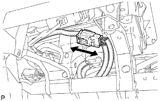
37. DISCONNECT PASSENGER AIRBAG CONNECTOR


F050426E01
  1. Disconnect the airbag connector.


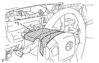
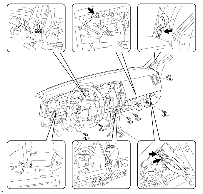
38. REMOVE INSTRUMENT PANEL SUB-ASSEMBLY


    E232399E01
  1. Tape the steering column cover upper and steering wheel sub-assembly with protective tape.
    Text in Illustration 
    *1
    Protective Tape

  1. Disengage the 4 clamps and disconnect the 4 connectors.


  1. Remove the 8 bolts, nut and instrument panel sub-assembly with passenger airbag assembly.


    E232400E01


39. REMOVE NO. 1 SPEAKER ASSEMBLY WITH BOX
(Click here)


40. REMOVE REAR SEAT CUSHION ASSEMBLY
(Click here)


41. REMOVE BACK PANEL GARNISH HOLE PLUG

HINT:
Follow the same procedure to remove all hole plugs.


    B205282
  1. Disengage the 4 claws and remove the 2 back panel garnish hole plugs.


42. REMOVE BACK PANEL TRIM COVER

HINT:
Follow the same procedure as for the opposite side.


    E212090
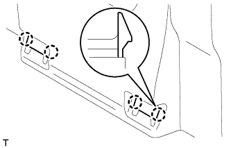
  1. Disengage the 2 claws and the 2 guides, remove the back panel trim cover.


43. REMOVE BACK PANEL TRIM


    E212020
  1. Remove the 2 clips.

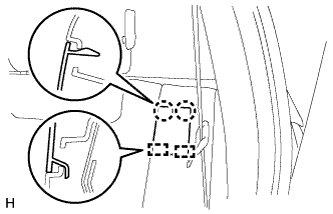
  1. Disengage the 8 claws and 14 clips, and remove the back panel trim.


44. REMOVE QUARTER TRIM LOWER PANEL LH


    B205284
  1. Remove the bolt and floor anchor of the rear seat belt outer.


    B205285
  1. Disengage the claw and 2 clips, and remove the quarter trim lower panel.


45. REMOVE QUARTER TRIM LOWER PANEL RH

HINT:
Follow the same procedures as for the quarter trim lower panel LH.


46. REMOVE ROOF SIDE INNER GARNISH LH


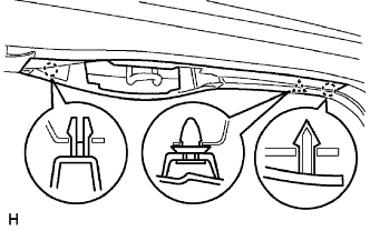
    B087451E01
  1. Disengage the 2 claws and clip, and remove the roof side inner garnish.


47. REMOVE ROOF SIDE INNER GARNISH RH

HINT:
Follow the same procedures as for the roof side inner garnish LH.


48. REMOVE QUARTER INSIDE TRIM BOARD LH


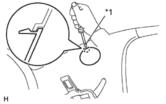
    B087452E03
  1. Using a screwdriver with its tip taped in protective tape, disengage the claw and open the cover.
    Text in Illustration 
    *1
    Protective Tape


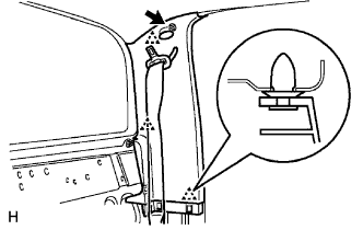
    B087453E01
  1. Remove the screw.

  1. Disengage the 3 clips and remove the quarter inside trim board.


49. REMOVE QUARTER INSIDE TRIM BOARD RH

HINT:
Follow the same procedures as for the quarter inside trim board LH.


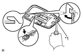
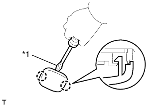
50. REMOVE ROOM LIGHT ASSEMBLY


    E232366E01
  1. Using a screwdriver with its tip taped in protective tape, disengage the 2 claws and remove the room light lens.
    Text in Illustration 
    *1
    Protective Tape


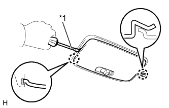
    B087455E04
  1. Using a screwdriver with its tip taped in protective tape, disengage the 2 claws.
    Text in Illustration 
    *1
    Protective Tape

  1. Disconnect the room light connector and remove the room light.


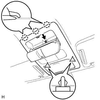
51. REMOVE ROOF CONSOLE BOX ASSEMBLY


    E232367
  1. Remove the screw.

  1. Disengage the 2 clips and 3 claws.

  1. Disconnect the connectors and remove the roof console box assembly.


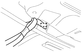
    B290415
  1. Using a clip remover, remove the wire harness clamp.


52. REMOVE ASSIST GRIP PLUG

HINT:
Follow the same procedures as for the opposite side.


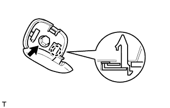
    B205278E02
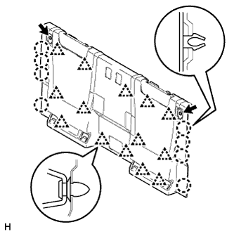
  1. Using a screwdriver with its tip taped in protective tape, disengage the 2 claws and open the cover.
    Text in Illustration 
    *1
    Protective Tape


    B205279
  1. Remove the screw.

  1. Disengage the claw and remove the assist grip plug.


53. REMOVE VISOR ASSEMBLY LH


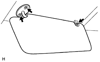
    B087457E01
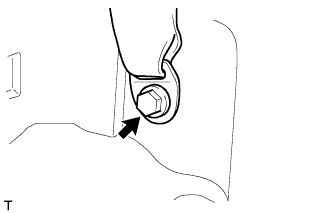
  1. Remove the 2 screws.

  1. Remove the visor from the visor holder.


54. REMOVE VISOR ASSEMBLY RH
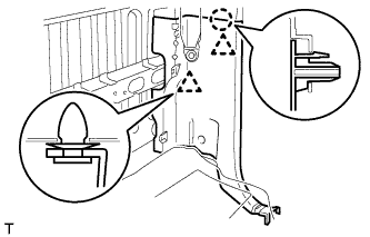
HINT:
Follow the same procedures as for the visor assembly LH.


55. REMOVE VISOR HOLDER

HINT:
Follow the same procedures as for the opposite side.


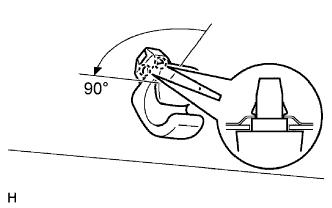
    B087458E02
  1. Turn the visor holder 90° counterclockwise and remove it.


56. REMOVE COAT HOOK

HINT:
Follow the same procedures as for the opposite side.


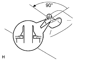
    B087459E02
  1. Turn the coat hook 90° counterclockwise and remove it.


57. REMOVE ROOF HEADLINING ASSEMBLY


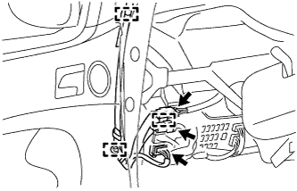
    B290416
  1. Disconnect the 3 roof wire connectors.

  1. Using a clip remover, remove the wire harness clamps.


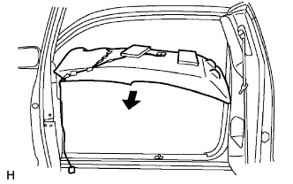
    B087460E01
  1. Remove the roof headlining from the vehicle.


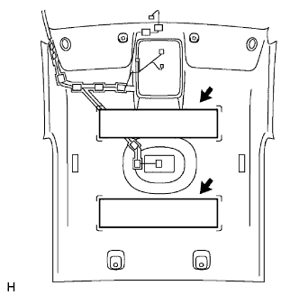
58. REMOVE ROOF HEADLINING PAD


    B087461E01
  1. Remove the 2 roof headlining pads from the roof headlining.


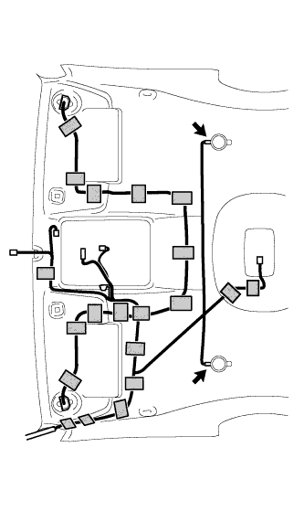
59. REMOVE ROOF WIRE


    B290419
  1. w/ Vanity light:

    1. Disconnect the 2 roof speaker connectors.

    2. Remove the 20 tapes and roof wire.


    B290420
  1. w/o Vanity Light:

    1. Disconnect the 2 roof speaker connectors.

    2. Remove the 9 tapes and roof wire.