FRONT AXLE HUB (for 2WD) > INSTALLATION |
| 1. INSTALL FRONT AXLE HUB |
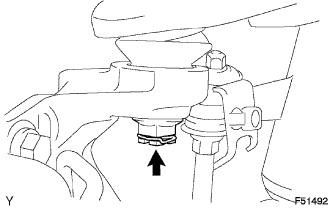
| 2. INSTALL FRONT SUSPENSION UPPER ARM |
|
Install the upper arm with a new nut.
Install the clip.
| 3. INSTALL FRONT SUSPENSION LOWER ARM |
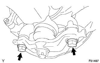 |
Install the front lower ball joint attachment LH with the 2 bolts.
| 4. INSTALL TIE ROD END SUB-ASSEMBLY |
Install the tie rod end onto the steering knuckle arm.
Install the nut.
Install a new cotter pin.
| 5. INSTALL FRONT DISC |
| 6. INSTALL FRONT DISC BRAKE CALIPER ASSEMBLY |
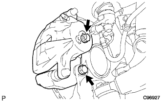 |
Install the brake caliper with the 2 bolts.
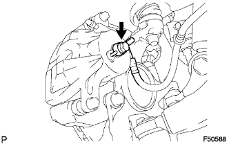 |
Install a new gasket and flexible hose with the union bolt.
| 7. INSTALL FRONT FLEXIBLE HOSE |
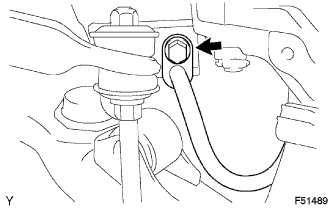 |
Install the front flexible hose with the bolt.
| 8. INSTALL FRONT SPEED SENSOR |
Install the speed sensor front with the bolt.
| 9. INSTALL SKID CONTROL SENSOR WIRE |
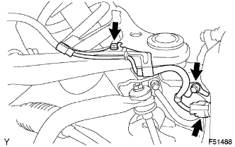 |
Install the skid control sensor wire with the 2 bolts.
Connect the speed sensor connector.
| 10. INSTALL FRONT WHEEL |
| 11. CONNECT CABLE TO NEGATIVE BATTERY TERMINAL |
| 12. FILL RESERVOIR WITH BRAKE FLUID (for Hydraulic Brake Booster) |
| 13. FILL RESERVOIR WITH BRAKE FLUID (for Vacuum Brake Booster) |
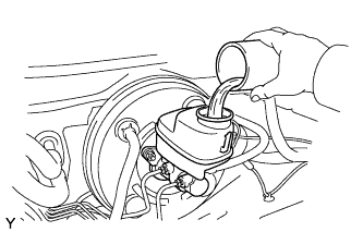 |
| 14. BLEED MASTER CYLINDER (for Vacuum Brake Booster) |
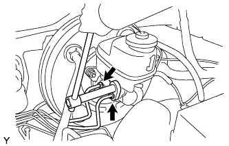 |
Using a union nut wrench, separate the brake tubes from the master cylinder.
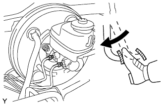 |
Slowly depress the brake pedal and hold it there (Step A).
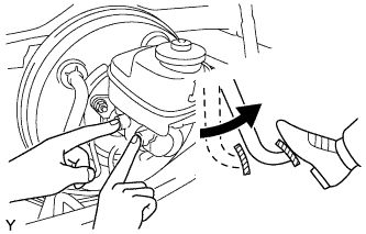 |
Block the outer holes with your fingers, and release the brake pedal (Step B).
Repeat steps A and B 3 or 4 times.
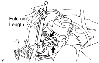 |
Using a union nut wrench, install the brake tubes into the master cylinder.
| 15. BLEED BRAKE LINE (for Hydraulic Brake Booster) |
Turn the ignition switch to ON, and wait until the pump motor has stopped.
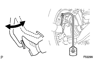 |
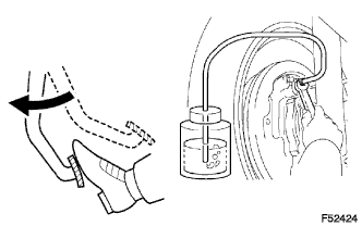
Front brake line.
Connect the vinyl tube to the brake caliper.
Depress the brake pedal several times, then loosen the bleeder plug with the pedal held down (step D).
At the point when the fluid stops coming out, tighten the bleeder plug, then release the brake pedal (step E).
Repeat step D and E until all the air in the fluid has been bled out.
Repeat the above procedures to bleed the other brake line.
 |
Rear brake line.
Connect the vinyl tube to the wheel cylinder.
Depress the brake pedal, hold it, and then loosen the bleeder plug.
Loosen the bleeder plug and release air.
When the air is completely bled out of the brake fluid through the bleeder plug, tighten the bleeder plug.
Repeat the above procedures to bleed the other brake line.
| 16. BLEED BRAKE LINE (for Vacuum Brake Booster) |
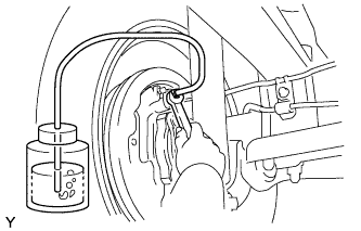 |
Connect a vinyl tube to the bleeder plug.
Depress the brake pedal several times, and then loosen the bleeder plug with the pedal depressed (Step C).
At the point where the fluid stops coming out, tighten the bleeder plug, and then release the brake pedal (Step D).
Repeat steps C and D until all the air in the fluid is completely bled out.
Tighten the bleeder plug.
Repeat the above procedure to bleed the air out of the brake line for each wheel.
| 17. INSPECT FLUID LEVEL IN RESERVOIR (for Hydraulic Brake Booster) |
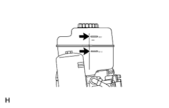 |
Turn the ignition switch to OFF, and depress the brake pedal more than 40 times (until the pedal reaction feels light and pedal stroke becomes longer), and adjust the fluid level to the MAX level.
When the ignition switch is turned to the ON, brake fluid is sent to the accumulator and the fluid level decreases by approximately 5 mm from the level when the ignition switch is off (normal).
| 18. INSPECT FLUID LEVEL IN RESERVOIR (for Vacuum Brake Booster) |
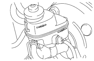 |
Check the fluid level.
If the brake fluid level is lower than the MIN line, check for leaks and inspect the disc brake pads. If necessary, refill the reservoir with brake fluid to the MAX line after repair or replacement.
| 19. INSPECT FOR BRAKE FLUID LEAK |
| 20. CHECK VSC SENSOR SIGNAL (for Hydraulic Brake Booster) |
| 21. CHECK VSC SENSOR SIGNAL (for Vacuum Brake Booster) |
| 22. INSPECT AND ADJUST FRONT WHEEL ALIGNMENT |