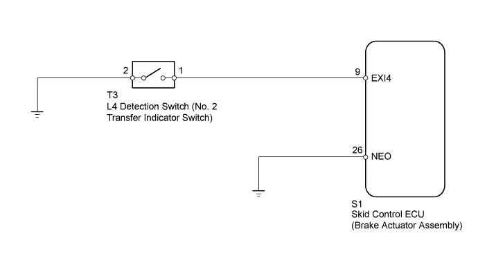
DTC C1268 Transfer L4 Position Switch Circuit |
| DTC Code | DTC Detection Condition | Trouble Area |
| C1268 |
|
|
| 1.INSPECT L4 DETECTION SWITCH |
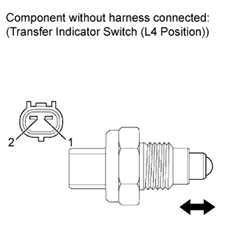 |
Disconnect the L4 detection switch (No. 2 transfer indicator switch) connector.
Measure the resistance according to the value(s) in the table below.
| Tester Connection | Switch Condition | Specified Condition |
| 1 - 2 | Pushed | Below 1 Ω |
| 1 - 2 | Free | 10 kΩ or higher |
|
| ||||
| OK | |
 |
| 2.CHECK HARNESS AND CONNECTOR (SKID CONTROL ECU - L4 DETECTION SWITCH) |
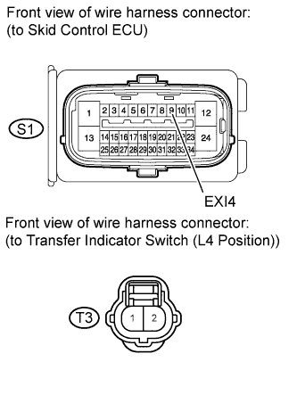 |
Disconnect the skid control ECU (brake actuator assembly) connector.
Disconnect the L4 detection switch (No. 2 transfer indicator switch) connector.
Measure the resistance according to the value(s) in the table below.
| Tester Connection | Condition | Specified Condition |
| S1-9 (EXI4) - T3-1 | Always | Below 1 Ω |
| S1-9 (EXI4) - Body ground | Always | 10 kΩ or higher |
| T3-2 - Body ground | Always | Below 1 Ω |
|
| ||||
| OK | |
|
| 3.CHECK HARNESS AND CONNECTOR (SKID CONTROL ECU - BODY GROUND) |
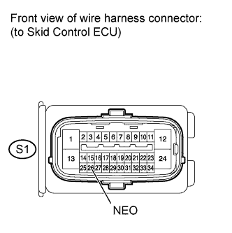 |
Disconnect the skid control ECU (brake actuator assembly) connector.
Measure the resistance according to the value(s) in the table below.
| Tester Connection | Condition | Specified Condition |
| S1-26 (NEO) - Body ground | Always | Below 1 Ω |
|
| ||||
| OK | |
|
| 4.CONFIRM DTC |
Clear the DTC (Click here).
Check if the same DTCs are recorded.
| Result | Proceed to |
| DTC output | A |
| DTC not output | B |
|
| ||||
| A | ||
 | ||
| ||
