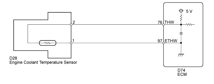
DTC P0115 Engine Coolant Temperature Circuit Malfunction |
DTC P0117 Engine Coolant Temperature Circuit Low Input |
DTC P0118 Engine Coolant Temperature Circuit High Input |
| DTC Code | DTC Detection Condition | Trouble Area |
| P0115 | Open or short in ECT sensor circuit for 0.5 seconds (1 trip detection logic) |
|
| P0117 | Short in ECT sensor circuit for 0.5 seconds (1 trip detection logic) |
|
| P0118 | Open in ECT sensor circuit for 0.5 seconds (1 trip detection logic) |
|
| Temperature Displayed | Malfunction |
| -40°C (-40°F) | Open circuit |
| 140°C (284°F) or higher | Short circuit |
| Related DTCs | P0115: ECT sensor range check (Fluctuating) P0117: ECT sensor range check (Low voltage) P0118: ECT sensor range check (High voltage) |
| Required Sensors/Components (Main) | ECT sensor |
| Required Sensors/Components (Related) | - |
| Frequency of Operation | Continuous |
| Duration | 0.5 seconds |
| MIL Operation | Immediate |
| Sequence of Operation | None |
| Monitor runs whenever following DTCs not present | None |
| ECT sensor voltage | Less than 0.14 V, or higher than 4.91 V |
| ECT sensor voltage [ECT] | Less than 0.14 V [More than 140°C (284°F)] |
| ECT sensor voltage [ECT] | Higher than 4.91 V [Less than -40°C (-40°F)] |
| ECT sensor voltage [ECT] | 0.14 to 4.91 V [-40 to 140°C (-40 to 284°F)] |
| 1.READ OUTPUT DTC |
Connect the Techstream to the DLC3.
Turn the ignition switch to ON and turn the Techstream ON.
Enter the following menus: Powertrain / Engine and ECT / Trouble Codes.
Read DTCs.
| Result | Proceed to |
| P0115 is output | A |
| P0117 is output | B |
| P0118 is output | C |
|
| ||||
|
| ||||
| A | |
 |
| 2.READ VALUE USING TECHSTREAM (ENGINE COOLANT TEMPERATURE) |
Connect the Techstream to the DLC3.
Turn the ignition switch to ON.
Turn the Techstream ON.
Enter the following menus: Powertrain / Engine and ECT / Data List / All Data / Coolant Temp.
Read the value displayed on the Techstream.
| Result | Proceed to |
| -40°C (-40°F) | A |
| 140°C (284°F) or higher | B |
| Between 80 and 100°C (176 and 212°F) | C |
|
| ||||
|
| ||||
| A | |
|
| 3.READ VALUE USING TECHSTREAM (CHECK FOR OPEN IN WIRE HARNESS) |
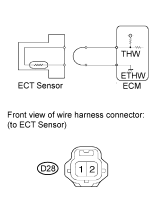 |
Disconnect the D28 ECT sensor connector.
Connect terminals 1 and 2 of the ECT sensor connector on the wire harness side.
Connect the Techstream to the DLC3.
Turn the ignition switch to ON.
Turn the Techstream ON.
Enter the following menus: Powertrain / Engine and ECT / Data List / All Data / Coolant Temp.
Read the value displayed on the Techstream.
|
| ||||
| OK | ||
 | ||
| ||
| 4.CHECK HARNESS AND CONNECTOR (ENGINE COOLANT TEMPERATURE SENSOR - ECM) |
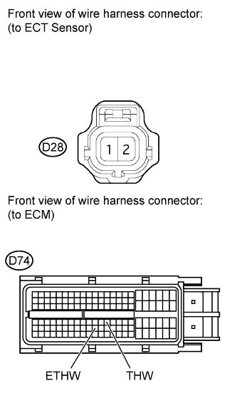 |
Disconnect the D28 ECT sensor connector.
Disconnect the D74 ECM connector.
Measure the resistance according to the value(s) in the table below.
| Tester Connection | Condition | Specified Condition |
| D28-2 - D74-76 (THW) | Always | Below 1 Ω |
| D28-1 - D74-97 (ETHW) | Always | Below 1 Ω |
|
| ||||
| OK | ||
| ||
| ||
| 5.READ VALUE USING TECHSTREAM (CHECK FOR SHORT IN WIRE HARNESS) |
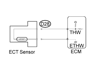 |
Disconnect the D28 ECT sensor connector.
Connect the Techstream to the DLC3.
Turn the ignition switch to ON.
Turn the Techstream ON.
Enter the following menus: Powertrain / Engine and ECT / Data List / All Data / Coolant Temp.
Read the value displayed on the Techstream.
|
| ||||
| OK | ||
| ||
| ||
| 6.CHECK HARNESS AND CONNECTOR (ENGINE COOLANT TEMPERATURE SENSOR - ECM) |
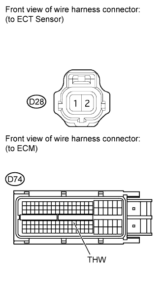 |
Disconnect the D28 ECT sensor connector.
Disconnect the D74 ECM connector.
Measure the resistance according to the value(s) in the table below.
| Tester Connection | Condition | Specified Condition |
| D28-2 or D74-76 (THW) - Body ground | Always | 10 kΩ or higher |
|
| ||||
| OK | ||
| ||
| ||

