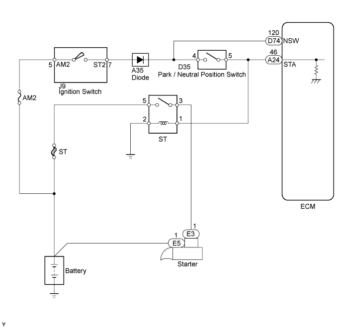
DTC P0617 Starter Relay Circuit High |
| DTC No. | DTC Detection Condition | Trouble Area |
| P0617 | When conditions (a), (b) and (c) met, positive (+B) battery voltage 10.5 V or more applied to ECM for 20 seconds (1 trip detection logic)
|
|
| Related DTCs | P0617: Starter signal |
| Required Sensors/Components (Main) | ST relay, PNP switch and Ignition switch |
| Required Sensors/Components (Related) | Vehicle Speed Sensor (VSS), Crankshaft Position (CKP) sensor |
| Frequency of Operation | Continuous |
| Duration | 20 seconds |
| MIL Operation | Immediate |
| Sequence of Operation | None |
| Monitor runs whenever following DTCs not present | None |
| Battery voltage | 10.5 V or more |
| Vehicle speed | 20 km/h (12.5 mph) or more |
| Engine speed | 1000 rpm or more |
| Starter signal | ON |
| 1.READ VALUE USING TECHSTREAM (STARTER SIGNAL) |
Connect the Techstream to the DLC3.
Turn the ignition switch to ON and turn the Techstream ON.
Enter the following menus: Powertrain / Engine and ECT / Data List / All Data / Starter Signal.
Check the value displayed on the Techstream when the ignition switch is turned to the ON and START positions.
| Ignition Switch Position | Starter Signal |
| ON | OFF |
| START | ON |
|
| ||||
| OK | ||
 | ||
| ||
| 2.INSPECT PARK/NEUTRAL POSITION SWITCH ASSEMBLY |
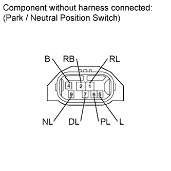 |
Disconnect the D35 PNP switch connector.
Measure the resistance according to the value(s) in the table below.
| Tester Connection | Condition | Specified Condition |
| 4 (B) - 5 (L) | Shift lever position P | Below 1 Ω |
| Shift lever position N | Below 1 Ω | |
| Shift lever position not on P or N | 10 kΩ or higher |
| Result | Proceed to |
| NG | A |
| OK | B |
|
| ||||
| A | |
 |
| 3.REPLACE PARK/NEUTRAL POSITION SWITCH ASSEMBLY |
Replace the park / neutral position switch (Click here).
| NEXT | |
|
| 4.READ VALUE USING TECHSTREAM (STARTER SIGNAL) |
Connect the Techstream to the DLC3.
Turn the ignition switch to ON and turn the Techstream ON.
Enter the following menus: Powertrain / Engine and ECT / Data List / All Data / Starter Signal.
Check the value displayed on the Techstream when the ignition switch is turned to the ON and START positions.
| Ignition Switch Position | Starter Signal |
| ON | OFF |
| START | ON |
|
| ||||
| OK | ||
| ||
| ||
| 5.INSPECT IGNITION SWITCH ASSEMBLY |
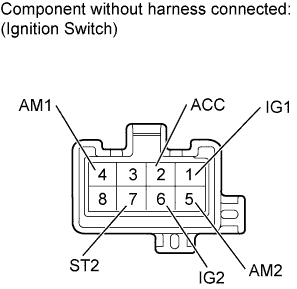 |
Disconnect the J9 ignition switch connector.
Measure the resistance according to the value(s) in the table below.
| Tester Connection | Switch Condition | Specified Condition |
| 5 (AM2) - 7 (ST2) | Ignition switch position LOCK | 10 kΩ or higher |
| Ignition switch position START | Below 1 Ω |
| Result | Proceed to |
| NG | A |
| OK | B |
|
| ||||
| A | |
|
| 6.REPLACE IGNITION SWITCH ASSEMBLY |
Replace the ignition switch (Click here).
| NEXT | |
|
| 7.READ VALUE USING TECHSTREAM (STARTER SIGNAL) |
Connect the Techstream to the DLC3.
Turn the ignition switch to ON and turn the Techstream ON.
Enter the following menus: Powertrain / Engine and ECT / Data List / All Data / Starter Signal.
Check the value displayed on the Techstream when the ignition switch is turned to the ON and START positions.
| Ignition Switch Position | Starter Signal |
| ON | OFF |
| START | ON |
|
| ||||
| OK | ||
| ||
| ||
| 8.REPAIR OR REPLACE HARNESS OR CONNECTOR (PNP SWITCH - STA TERMINAL OF ECM) |
| NEXT | |
|
| 9.CHECK WHETHER DTC OUTPUT RECURS |
Connect the Techstream to the DLC3.
Turn the ignition switch to ON.
Turn the Techstream ON.
Clear DTCs (Click here).
Drive the vehicle at more than 20 km/h (12.43 mph) for over 20 seconds.
Enter the following menus: Powertrain / Engine and ECT / Trouble Codes.
Read DTCs.
| Result | Proceed to |
| P0617 is output | A |
| No DTC is output | B |
|
| ||||
| A | ||
| ||
| ||

