Home › ENGINE ยท 1GR-FE › ENGINE MECHANICAL › ENGINE

ENGINE > ON-VEHICLE INSPECTION

for Preparation Click here


1. INSPECT ENGINE COOLANT
  1. Remove the radiator cap.

    CAUTION:
    Do not remove the radiator cap while the engine and radiator are still hot. Pressurized, hot engine coolant and steam may be released and cause serious burns.

  1. Check if there are any excessive deposits of rust or scales around the radiator cap and radiator filler hole. Also, the coolant should be free of oil.
    If excessively dirty, clean the coolant passage and replace the coolant.

  1. Install the radiator cap.


2. INSPECT ENGINE OIL


3. INSPECT BATTERY

NOTICE:
If the battery is weak or if the engine is difficult to start, perform the following procedures.

  1. Check the battery for damage and deformation. If severe damage, deformation or leakage is found, replace the battery.

  1. Check the electrolyte quantity of each cell.

    1. For maintenance-free batteries:

      1. If the electrolyte quantity is below the lower line, replace the battery.
      2. If the electrolyte quantity is above the lower line, check the battery voltage when cranking the engine. If the voltage is less than 9.6 V, recharge or replace the battery.

        HINT:
        Before checking the battery voltage, turn off all the electrical systems (headlights, blower motor, rear defogger, etc.).

    2. For non-maintenance-free batteries:

      1. If the electrolyte quantity is below the lower line, add distilled water to each cell. Then, recharge the battery and check the electrolyte's specific gravity.

        Standard specific gravity:
        1.25 to 1.29 at 20°C (68°F)

      1. If the electrolyte quantity is above the lower line, check the battery voltage when cranking the engine. If the voltage is less than 9.6 V, recharge or replace the battery.

        HINT:
        Before checking the battery voltage, turn off all the electrical systems (headlights, blower motor, rear defogger, etc.).

  1. Turn the ignition switch off and turn on the headlight for 20 to 30 seconds. This will remove the surface charge from the battery.


    A001260E02
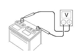
  1. Measure the battery voltage between the negative (-) and positive (+) terminals of the battery.
    Standard voltage:
    12.5 to 12.9 V at 20°C (68°F)

    If the voltage is below the specification, recharge the battery.


    Z011580E01
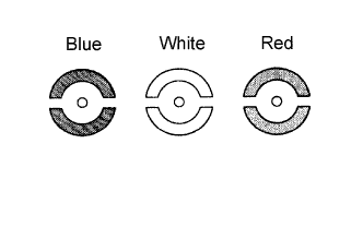
  1. Reference:
    The indicator shows the battery condition.

    HINT:
    1. Blue: OK
    2. White: Charging necessary
    3. Red: Insufficient electrolyte


4. INSPECT AIR CLEANER FILTER ELEMENT SUB-ASSEMBLY


5. INSPECT IGNITION TIMING

NOTICE:
  1. Turn all electrical systems OFF.
  1. Perform the inspection when the cooling fan motor is turned OFF.

  1. Warm up the engine.

  1. When using the Techstream:

    1. Connect the Techstream to the DLC3.

    2. Enter the following menus:
      Select: Powertrain / Engine and ECT / Data List / All Data / IGN Advance

    3. Inspect the ignition timing during idling.

      Standard ignition timing:
      8 to 12° BTDC @ idling (transmission in neutral position and A/C switch OFF)

    4. Check that the ignition timing advances immediately when the engine speed is increased.


    H102392E79
  1. When not using Techstream:

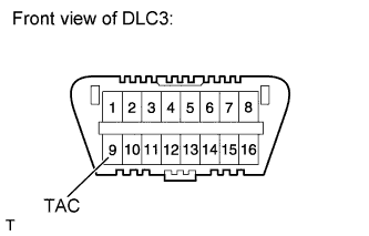
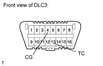
    1. Using SST, connect terminals 13 (TC) and 4 (CG) of the DLC3.

      SST
      09843-18040  

      NOTICE:
      Be sure not to improperly connect the terminals. This may damage the engine.

    2. Remove the air cleaner cap.


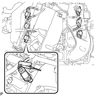
    3. A158636
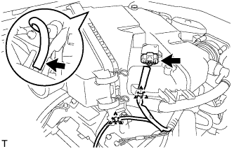
    4. Pull out the wire harness as shown in the illustration.

    5. Connect the tester probe of a timing light to the wire of the ignition coil connector for the No. 1 cylinder.
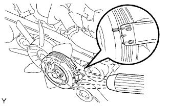
      NOTICE:
      1. Use a timing light that detects primary signals.
      1. After checking, be sure to wrap the wire harness with tape.


    6. A076316E01
    7. Inspect the ignition timing during idling.

      Standard ignition timing:
      8 to 12° BTDC @ idling (transmission in neutral position and A/C switch OFF)

    8. Remove SST from the DLC3.

    9. Inspect the ignition timing during idling.

      Standard ignition timing:
      7 to 24° BTDC @ idling (transmission in neutral position and A/C switch OFF)

    10. Disconnect the timing light from the engine.

    11. Install the air cleaner cap.


6. INSPECT ENGINE IDLING SPEED

NOTICE:
  1. Turn all the electrical systems OFF.
  1. Perform the inspection when the cooling fan motor is turned OFF.

  1. Warm up the engine.

  1. When using the Techstream:

    1. Connect the Techstream to the DLC3.

    2. Enter the following menus:
      Select: Powertrain / Engine and ECT / Data List / All Data / Engine Speed

    3. Inspect the engine idling speed.

      Standard idling speed:
      650 to 750 rpm (transmission in neutral position and A/C switch OFF)


    H102392E88
  1. When not using the Techstream:

    1. Using SST, connect terminal 9 (TAC) of the DLC3.

      SST
      09843-18030  

    2. Race the engine at 2500 rpm for approximately 90 seconds.

    3. Inspect the engine idling speed.

      Standard idling speed:
      650 to 750 rpm (transmission in neutral position and A/C switch OFF)


7. INSPECT COMPRESSION
  1. Warm up and stop the engine.

  1. Remove the 2 bolts, 2 screws and No. 1 engine under cover.

  1. Drain engine coolant .

  1. Remove the front wiper motor and link (Click here).

  1. Remove the front cowl top outer panel .
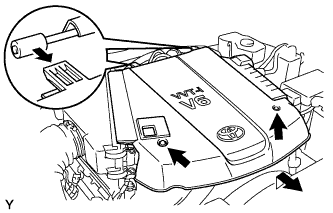


    A112983
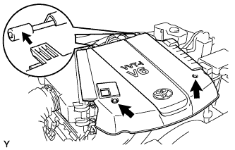
  1. Remove the 2 nuts and V-bank cover.

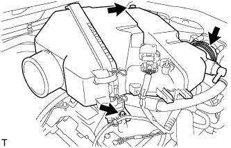
  1. Loosen the clamp and remove the No. 2 air cleaner hose.
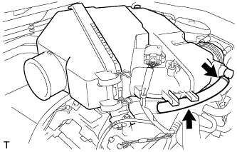


    A151812
  1. Disconnect the ventilation hose.


    A151769
  1. Disconnect the MAF connector.

  1. Using a clip remover, detach the 2 wire harness clamps.

  1. Disconnect the vacuum hose.


    A151770
  1. Loosen the hose clamp and remove the 2 bolts and air cleaner with element.

  1. Remove the intake air surge tank .

  1. Remove the 6 ignition coils.

  1. Remove the 6 spark plugs.

  1. Disconnect the 6 fuel injector connectors.


    A076317E02
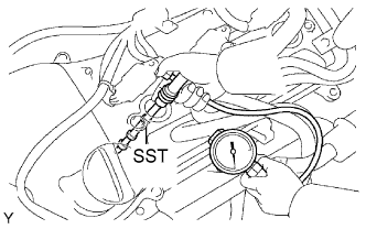
  1. Inspect the cylinder compression pressure.

    1. Insert SST (compression gauge) into the spark plug hole (Procedure "A").

      SST
      09992-00500  

    2. While cranking the engine, measure the compression pressure (Procedure "B").

      Compression pressure:
      1300 kPa (13.3 kgf/cm2, 189 psi)

      Minimum pressure:
      1000 kPa (10.2 kgf/cm2, 145 psi)

      Difference between each cylinder:
      100 kPa (1.0 kgf/cm2, 15 psi)

      HINT:
      1. Use a fully-charged battery so that the engine speed can be increased to 250 rpm or more.
      2. Measure the compression in as short a time as possible.

    3. Repeat procedures "A" and "B" for each cylinder.

    4. If the cylinder compression is low, pour a small amount of engine oil into the cylinder through the spark plug hole and repeat procedures "A" and "B" for cylinders with low compression.

      1. If adding oil increases the compression, the piston rings and/or cylinder bore may be worn or damaged.
      2. If pressure stays low, a valve may be stuck or seated improperly, or there may be leakage from the gasket.

  1. Connect the 6 injector connectors.

  1. Install the 6 spark plugs.

    Torque:
    20 N*m{ 204 kgf*cm , 15 ft.*lbf }

  1. Install the 6 ignition coils.

    Torque:
    9.0 N*m{ 92 kgf*cm , 80 in.*lbf }

  1. Install the intake air surge tank .

  1. Install the air cleaner with element .

  1. Install the No. 2 air cleaner hose .


    A112983E01
  1. Install the V-bank cover with the 2 nuts.

    Torque:
    7.5 N*m{ 76 kgf*cm , 66 in.*lbf }

  1. Install the front cowl top outer panel .

  1. Install the wiper motor and link (Click here).

  1. Add engine coolant .

  1. Install the No. 1 engine under cover with the 2 bolts and 2 screws.

    Torque:
    for bolt:
    29 N*m{ 296 kgf*cm , 21 ft.*lbf }
    for screw:
    5.4 N*m{ 55 kgf*cm , 48 in.*lbf }


8. INSPECT CO/HC

HINT:
This check is to determine whether or not the idle CO/HC complies with regulations.

  1. Start the engine.

  1. Run the engine at 2500 rpm for approximately 180 seconds.
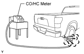


    A158629E01
  1. Insert the CO/HC meter testing probe at least 40 cm (1.31 ft) into the tailpipe during idling.

  1. Immediately check the CO/HC concentration during idling and/or at 2500 rpm.

    HINT:
    When carrying out the 2 modes (idling and 2500 rpm) test, the measurement orders are prescribed by the applicable local regulations.

  1. If the CO/HC concentration does not comply with regulations, perform troubleshooting in the order given below.

    1. Check the A/F sensor operation (Click here) and heated oxygen sensor operation (Click here).

    2. See the table below for possible causes, and then inspect and correct the corresponding causes if necessary.

      CO
      HC
      Symptom
      Causes
      Normal
      High
      Rough idling
      1. Faulty ignition:
        1. Incorrect timing
        2. Plugs are contaminated or shorted, or plug gaps are defective
      2. Incorrect valve clearance
      3. Leaky intake and exhaust valves
      4. Leaky cylinders
      Low
      High
      Rough idling
      (Fluctuating HC reading)
      1. Vacuum leaks:
        1. Ventilation hoses
        2. Intake manifold
        3. Throttle body
      2. Lean mixture causing misfire
      High
      High
      Rough idle
      (Black smoke from exhaust)
      1. Restricted air filter
      2. Faulty SFI system:
        1. Faulty pressure regulator
        2. Defective engine coolant temperature sensor
        3. Faulty mass air flow meter
        4. Faulty ECM
        5. Faulty injectors
        6. Faulty throttle position sensor