 |
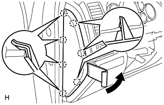
Using a moulding remover, detach the 7 claws and remove the side panel.
PARKING BRAKE CABLE > REMOVAL |
| 1. DISCONNECT CABLE FROM NEGATIVE BATTERY TERMINAL |
| 2. REMOVE INSTRUMENT SIDE PANEL LH |
|
Using a moulding remover, detach the 7 claws and remove the side panel.
| 3. REMOVE LOWER INSTRUMENT PANEL FINISH PANEL SUB-ASSEMBLY LH |
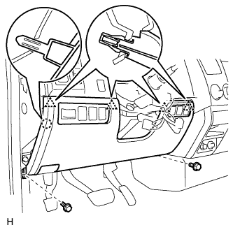 |
Remove the hood lock control lever.
Remove the 2 bolts.
Detach the 4 clips and claw.
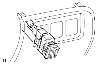 |
for Automatic Air Conditioning System:
Detach the 2 claws and remove the sensor.
Remove the finish panel and then disconnect the connectors.
| 4. REMOVE NO. 1 INSTRUMENT PANEL SAFETY PAD INSERT |
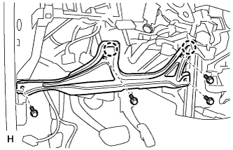 |
Remove the 4 bolts.
Detach the 2 claws.
Remove the safety pad and then disconnect the connector.
| 5. RELEASE PARKING BRAKE PEDAL |
| 6. DISCONNECT NO. 1 PARKING BRAKE CABLE ASSEMBLY |
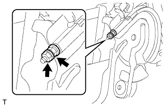 |
Remove the lock nut and adjustment nut.
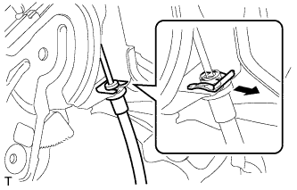 |
Remove the clip.
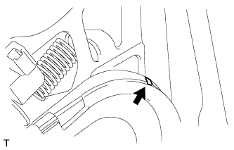 |
Using a screwdriver, slowly bend up the claw.
Disconnect the parking brake cable from the parking brake control pedal.
| 7. REMOVE FRONT NO. 3 EXHAUST PIPE SUB-ASSEMBLY (for 1GR-FE) |
for Regular Cab Standard Deck:
Remove the front No. 3 exhaust pipe .
| 8. REMOVE FRONT NO. 2 EXHAUST PIPE ASSEMBLY (for 1GR-FE) |
for Regular Cab Standard Deck:
Remove the front No. 2 exhaust pipe .
except Regular Cab Standard Deck:
Remove the front No. 2 exhaust pipe .
| 9. REMOVE FRONT NO. 2 EXHAUST PIPE ASSEMBLY (for 2UZ-FE) |
for Regular Cab Standard Deck:
Remove the front No. 2 exhaust pipe .
except Regular Cab Standard Deck:
Remove the front No. 2 exhaust pipe .
| 10. REMOVE FRONT NO. 3 EXHAUST PIPE SUB-ASSEMBLY (for 2UZ-FE) |
for Regular Cab Standard Deck:
Remove the front No. 3 exhaust pipe .
| 11. REMOVE FRONT NO. 3 EXHAUST PIPE SUB-ASSEMBLY (for 3UR-FE) |
for Regular Cab Standard Deck:
Remove the front No. 3 exhaust pipe .
| 12. REMOVE FRONT NO. 3 EXHAUST PIPE SUB-ASSEMBLY (for 3UR-FBE) |
for Regular Cab Standard Deck:
Remove the front No. 3 exhaust pipe .
| 13. REMOVE FRONT NO. 2 EXHAUST PIPE ASSEMBLY (for 3UR-FE) |
for Regular Cab Standard Deck:
Remove the front No. 2 exhaust pipe .
except Regular Cab Standard Deck:
Remove the front No. 2 exhaust pipe .
| 14. REMOVE FRONT NO. 2 EXHAUST PIPE ASSEMBLY (for 3UR-FBE) |
except Regular Cab Standard Deck:
Remove the front No. 2 exhaust pipe .
| 15. REMOVE NO. 1 PARKING BRAKE CABLE ASSEMBLY (for 3220 mm [10 ft. 6.8 in.] Wheelbase Type) |
Remove the adjustment nut and lock nut (labeled A).
Remove the bolt (labeled B) and cable retainer.
Remove the nut (labeled C) and clamp from the body.
Disconnect the clamp (labeled D) from the No. 1 parking brake cable.
Remove the 2 bolts (labeled E) and No. 1 parking brake cable from the inside of the vehicle.
Remove the 3 bolts (labeled F) and No. 1 cable support bracket.
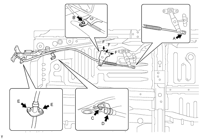
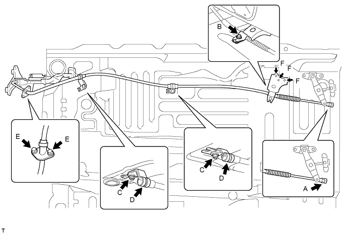
| 16. REMOVE NO. 1 PARKING BRAKE CABLE ASSEMBLY (for 3700 mm [12 ft. 1.7 in.] Wheelbase Type) |
Remove the adjustment nut and lock nut (labeled A).
Remove the bolt (labeled B) and cable retainer.
Remove the 2 nuts (labeled C) and 2 clamps from the body.
Disconnect the 2 clamps (labeled D) from the No. 1 parking brake cable.
Remove the 2 bolts (labeled E) and No. 1 parking brake cable from the inside of the vehicle.
Remove the 3 bolts (labeled F) and No. 1 cable support bracket.
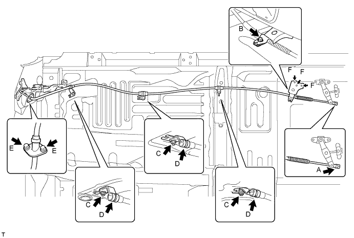
| 17. REMOVE NO. 1 PARKING BRAKE CABLE ASSEMBLY (for 4180 mm [13 ft. 8.6 in.] Wheelbase Type) |
Remove the adjustment nut and lock nut (labeled A).
Remove the bolt (labeled B) and cable retainer.
Remove the 3 nuts (labeled C) and 3 clamps from the body.
Disconnect the 3 clamps (labeled D) from the No. 1 parking brake cable.
Remove the 2 bolts (labeled E) and No. 1 parking brake cable from the inside of the vehicle.
Remove the 3 bolts (labeled F) and No. 1 cable support bracket.
| 18. REMOVE REAR WHEEL LH |
| 19. DISCONNECT REAR DISC BRAKE CYLINDER ASSEMBLY LH |
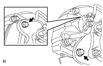 |
Remove the 2 bolts and disconnect the rear disc brake cylinder.
Hang the disc brake cylinder with a piece of wire.
| 20. REMOVE REAR DISC LH |
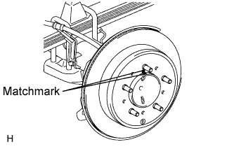 |
Put matchmarks on the rear disc and axle hub if planning to reuse the disc.
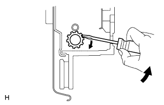 |
Turn the shoe adjuster until the disc turns freely, and then remove the disc.
| 21. REMOVE PARKING BRAKE SHOE RETURN SPRING LH |
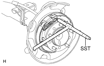 |
Using SST, remove the return spring.
| 22. REMOVE NO. 1 PARKING BRAKE SHOE ASSEMBLY LH |
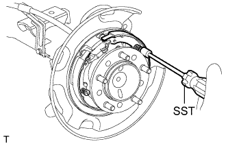 |
Using SST, remove the shoe hold down spring cup, compression spring and shoe hold down spring pin.
Disconnect the tension spring.
Remove the No. 1 parking brake shoe and shoe adjuster screw set.
| 23. REMOVE NO. 2 PARKING BRAKE SHOE ASSEMBLY LH |
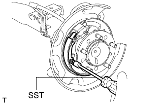 |
Using SST, remove the shoe hold down spring cup, compression spring and shoe hold down spring pin.
Remove the No. 2 parking brake shoe.
| 24. REMOVE PARKING BRAKE SHOE LEVER LH |
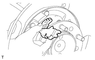 |
Disconnect the No. 3 parking brake cable from the parking brake shoe lever.
Remove the parking brake shoe lever.
| 25. REMOVE INTERMEDIATE LEVER TENSION SPRING |
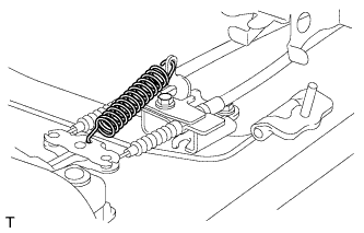 |
Remove the tension spring.
| 26. REMOVE NO. 2 CABLE RETAINER |
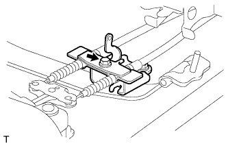 |
Remove the bolt and cable retainer.
| 27. REMOVE NO. 3 PARKING BRAKE CABLE ASSEMBLY |
Remove the 5 bolts and disconnect the No. 3 parking brake cable from the intermediate lever.
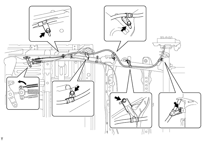
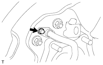 |
Remove the bolt and No. 3 parking brake cable from the rear axle carrier.
| 28. REMOVE REAR WHEEL RH |
| 29. DISCONNECT REAR DISC BRAKE CYLINDER ASSEMBLY RH |
| 30. REMOVE REAR DISC RH |
| 31. REMOVE PARKING BRAKE SHOE RETURN SPRING RH |
| 32. REMOVE NO. 1 PARKING BRAKE SHOE ASSEMBLY RH |
| 33. REMOVE NO. 2 PARKING BRAKE SHOE ASSEMBLY RH |
| 34. REMOVE PARKING BRAKE SHOE LEVER RH |
| 35. REMOVE NO. 2 PARKING BRAKE CABLE ASSEMBLY |
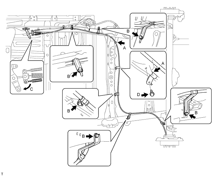
Disconnect the No. 2 parking brake cable from the 2 clamps (labeled A).
Remove the 5 bolts (labeled B) and disconnect the No. 2 parking brake cable from the intermediate lever (labeled C).
Remove the bolt (labeled D) and clamp.
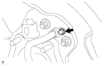 |
Remove the bolt and No. 2 parking brake cable from the rear axle carrier.
| 36. REMOVE PARKING BRAKE INTERMEDIATE LEVER SUB-ASSEMBLY |
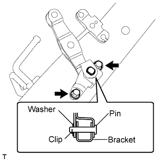 |
Remove the 2 bolts and intermediate lever with bracket.
Remove the clip, washer, pin and intermediate lever from the bracket.
| 37. REMOVE NO. 2 CABLE SUPPORT BRACKET |
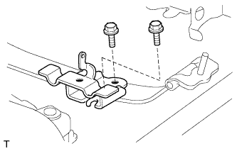 |
Remove the 2 bolts and bracket.