 |
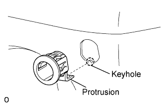
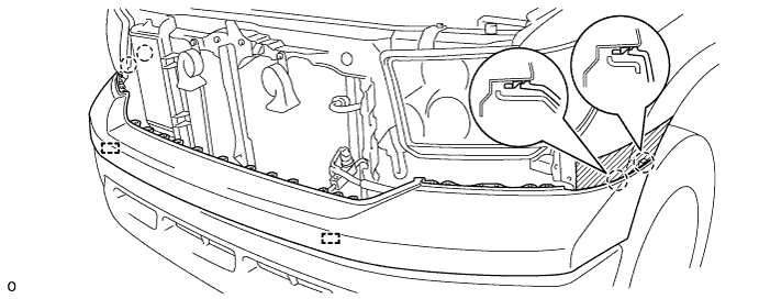
Align the keyhole and protrusion as shown in the illustration.
ULTRASONIC SENSOR (for Front Side) > INSTALLATION |
| 1. INSTALL NO. 1 ULTRASONIC SENSOR RETAINER |
|
Align the keyhole and protrusion as shown in the illustration.
Install the sensor retainer to the front bumper.
| 2. INSTALL NO. 1 ULTRASONIC SENSOR |
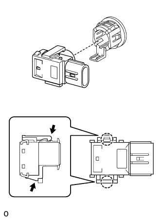 |
Attach the 2 claws to install the ultrasonic sensor.
| 3. INSTALL FRONT BUMPER COVER (for Resin Type Bumper) |
w/ Fog Light:
Connect the fog light connectors.
w/ Intuitive Parking Assist System:
Connect the ultrasonic sensor connectors.
Attach the 4 claws to install the bumper cover.
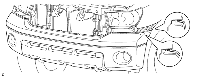
Install the 9 screws and 8 clips.
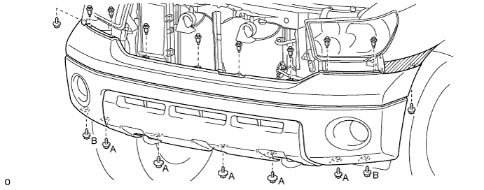
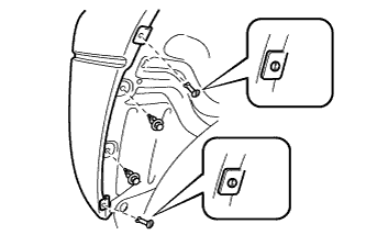 |
Install the 2 clips.
Install the 2 pin hold clips so that their grooves are vertical.
| 4. INSTALL FRONT BUMPER BAR |
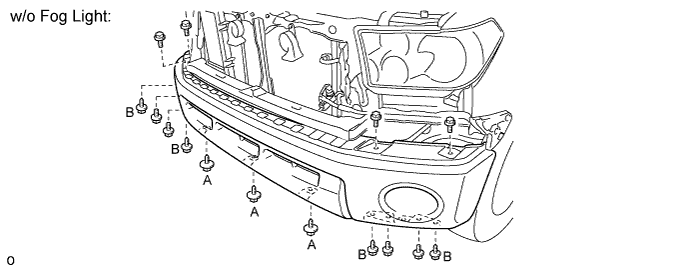
w/o Fog Light:
Install the front bumper bar.
w/ Intuitive Parking Assist System:
Connect the ultrasonic sensor connectors.
Install the bumper bar with the 8 bolts and 7 screws.
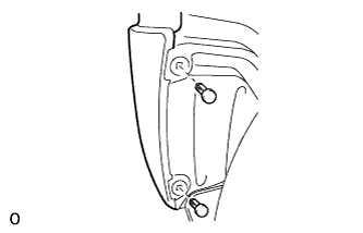 |
Install 2 new clips.
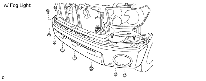
w/ Fog Light:
Install the front bumper bar.
w/ Intuitive Parking Assist System:
Connect the ultrasonic sensor connectors.
Install the bumper bar with the 8 bolts and 3 screws.
| 5. INSTALL FRONT BUMPER COVER SUB-ASSEMBLY |
Attach the 4 claws and 2 pins to install the bumper cover.
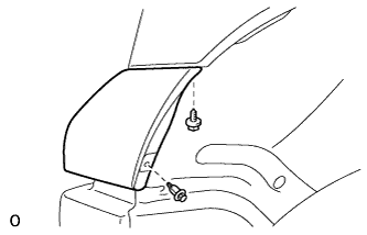 |
Install the screw and clip.
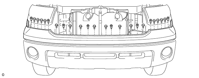
Install the 16 bolts and 8 clips.
| 6. INSTALL FRONT END PANEL RH (for Resin Type Bumper) |
| 7. INSTALL FRONT END PANEL LH (for Resin Type Bumper) |
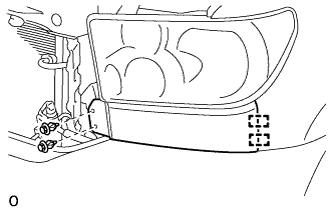 |
Attach the 2 pins to install the panel.
Install the 2 clips.
| 8. INSTALL FRONT END PANEL RH |
| 9. INSTALL FRONT END PANEL LH |
|
Attach the 2 pins to install the panel.
Install the 2 clips.
| 10. INSTALL FRONT FENDER SPLASH SHIELD SUB-ASSEMBLY RH (for Steel Type Bumper) |
| 11. INSTALL FRONT FENDER SPLASH SHIELD SUB-ASSEMBLY LH (for Steel Type Bumper) |
Connect the fog light connector.
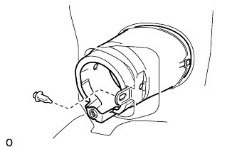 |
Install the clip.
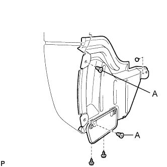 |
Install the front fender splash shield with the 2 screws, clip and 2 new clips labeled A.
| 12. CONNECT CABLE TO NEGATIVE BATTERY TERMINAL |
| 13. ADJUST FOG LIGHT |
Adjust the fog light (Click here).