 |
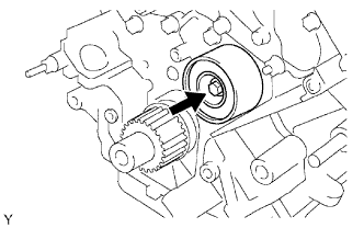
Install the idler with the bolt.
- Torque:
- 35 N*m{ 357 kgf*cm , 26 ft.*lbf }
TIMING BELT > INSTALLATION |
| 1. INSTALL NO. 2 TIMING BELT IDLER SUB-ASSEMBLY |
|
Install the idler with the bolt.
| 2. INSTALL NO. 1 TIMING BELT IDLER SUB-ASSEMBLY |
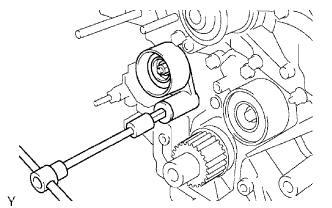 |
Using a 10 mm hexagon wrench, install the plate washer and idler with the bolt.
| 3. INSTALL TIMING BELT |
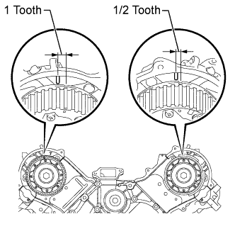 |
Set the No. 1 cylinder to TDC/compression.
Turn the hexagonal portion of the camshaft to align the timing marks of the camshaft timing pulleys and timing belt plates.
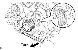 |
Using the pulley set bolt, turn the crankshaft to align the timing marks of the crankshaft timing pulley and oil pump body.
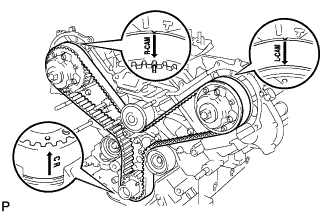 |
Install the timing belt.
Remove any oil or water from each pulley, and keep them clean.
Face the front mark (arrow) on the timing belt forward.
Set the timing belt on the crankshaft timing pulley.
Set the timing belt on the No. 2 timing belt idler.
Set the timing belt on the camshaft timing pulley (for bank 1).
Set the timing belt on the water pump pulley.
Set the timing belt on the camshaft timing pulley (for bank 2).
Set the timing belt on the No. 1 timing belt idler.
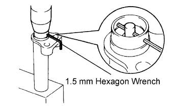 |
Install the belt tensioner.
Using a press, slowly press in the push rod using 981 to 9807 N (100 to 1000 kgf, 220.5 to 2204.7 lbf) of force.
Align the holes of the push rod and housing, and pass a 1.5 mm hexagon wrench through the holes to keep the setting position of the push rod.
Release the press.
Install the dust boot to the belt tensioner.
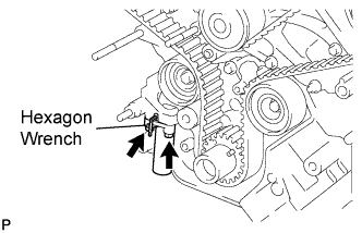 |
Temporarily install the belt tensioner with the 2 bolts.
Tighten the 2 bolts.
Using pliers, remove the 1.5 mm hexagon wrench from the timing belt tensioner.
| 4. CHECK NO. 1 CYLINDER TO TDC / COMPRESSION |
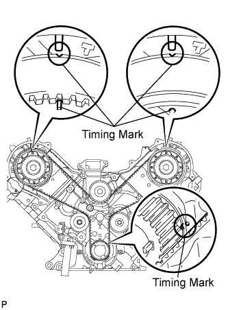 |
Using the pulley set bolt, slowly turn the crankshaft pulley 2 revolutions from the TDC to TDC.
Check that each pulley is aligned with each timing mark as shown in the illustration.
If the timing marks are not aligned, remove the timing belt and reinstall it.
Remove the pulley set bolt.
| 5. INSTALL NO. 1 CRANKSHAFT POSITION SENSOR PLATE |
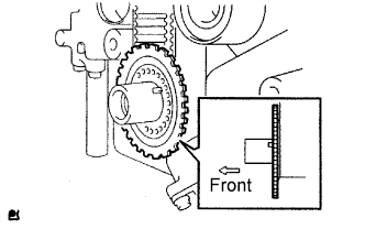 |
Install the sensor plate as shown in the illustration.
| 6. INSTALL NO. 1 TIMING BELT COVER |
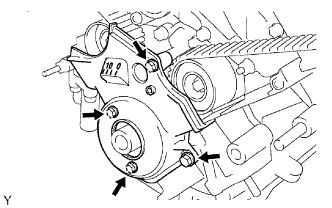 |
Install the cover spacer and gasket.
Install the timing belt cover with the 4 bolts.
| 7. INSTALL CRANKSHAFT PULLEY |
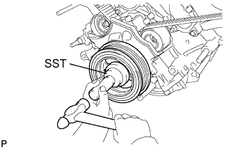 |
Align the pulley set key with the key groove of the crankshaft pulley.
Using SST and a hammer, tap in the crankshaft pulley.
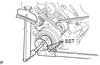 |
Using SST, install the pulley set bolt.
| 8. INSTALL FAN BRACKET SUB-ASSEMBLY |
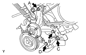 |
Install the fan bracket with the 2 bolts and 2 nuts.
| 9. INSTALL V-RIBBED BELT TENSIONER ASSEMBLY |
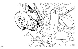 |
Install the belt tensioner with the bolt and 2 nuts.
| 10. INSTALL NO. 2 TIMING BELT COVER SUB-ASSEMBLY |
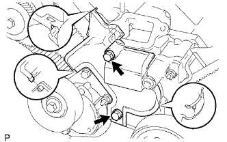 |
Install the timing belt cover and fit the claws and pins into each part.
Install the 2 bolts.
| 11. INSTALL NO. 3 TIMING BELT COVER SUB-ASSEMBLY LH |
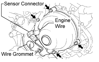 |
Pass the camshaft position sensor wire through the cover hole.
Install the cover with the 4 bolts.
Install the wire grommet to the belt cover.
Connect the sensor connector.
Install the sensor wire to the wire clamps on the cover.
Connect the engine wire to the 2 wire clamps on the cover.
| 12. INSTALL NO. 3 TIMING BELT COVER SUB-ASSEMBLY RH |
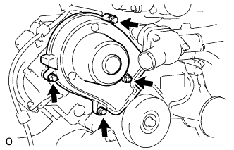 |
Install the cover with the 3 bolts and nut.
| 13. INSTALL NO. 2 IDLER PULLEY SUB-ASSEMBLY |
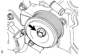 |
Install the idler pulley and cover plate with the bolt.
| 14. INSTALL OIL COOLER PIPE |
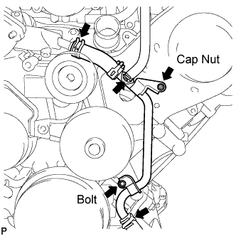 |
Using needle-nose pliers, grip the claws of the clamps and slide the clamps to connect the 3 water by-pass hoses.
Install the oil cooler pipe with the cap nut and bolt.
| 15. CONNECT COOLER COMPRESSOR ASSEMBLY |
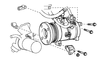 |
Connect the compressor. Then install it and the No. 1 compressor stay with the nut and 3 bolts.
Connect the connector.
| 16. INSTALL GENERATOR ASSEMBLY |
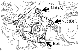 |
Install the generator with the bolt and 2 nuts.
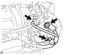 |
Connect the generator connector.
Connect the generator wire with the nut.
Install the terminal cap.
Install the harness bracket to the generator with the bolt.
| 17. CONNECT VANE PUMP ASSEMBLY |
Connect the vane pump with the nut and 2 bolts.
Connect the connector.
| 18. INSTALL FLUID COUPLING ASSEMBLY |
Set the fan pulley to the fan bracket.
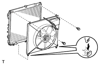 |
Set the fan together with the fan shroud into the vehicle.
Temporarily install the fan to the fan pulley with the 4 fluid coupling nuts.
Install the fan shroud with the 2 bolts.
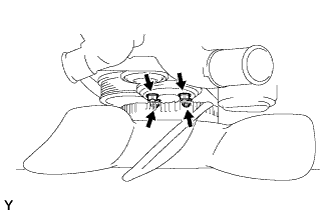 |
Tighten the 4 fluid coupling nuts.
| 19. INSTALL FAN AND GENERATOR V BELT |
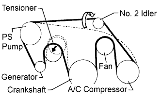 |
Set the V belt onto every part except the No. 2 idler pulley, as shown in the illustration.
Loosen the V belt by turning the belt tensioner counterclockwise.
Set the V belt to the No. 2 idler pulley.
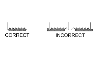 |
After installing the belt, check that it fits properly in the ribbed grooves.
Check by hand to confirm that the belt has not slipped out of the grooves on the bottom of the pulley.
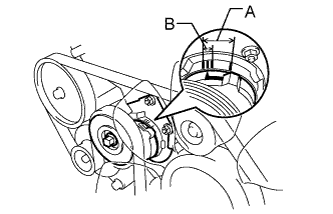 |
Check that the arrow on the belt tensioner is within area "A".
If it is outside area "A", replace the fan and generator V belt.
| 20. INSTALL RADIATOR HOSE OUTLET |
| 21. INSTALL RADIATOR HOSE INLET |
| 22. INSTALL AIR CLEANER ASSEMBLY |
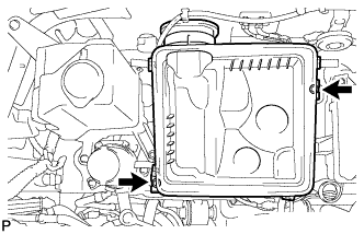 |
Install the air cleaner case with the 2 bolts.
Install the air cleaner element onto the air cleaner case.
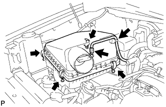 |
Install the air cleaner cap.
Fasten the 4 hook clamps.
Connect the MAF meter connector.
Attach the wire harness clamp.
| 23. INSTALL AIR CLEANER HOSE ASSEMBLY |
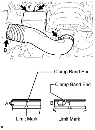 |
Install the air cleaner hose.
Connect the vacuum hose.
Connect the No. 2 ventilation hose.
| 24. INSTALL THROTTLE BODY COVER SUB-ASSEMBLY |
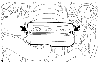 |
Install the throttle body cover sub-assembly with the 2 nuts.
| 25. ADD ENGINE COOLANT |
Add engine coolant.
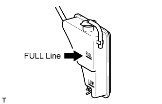 |
Slowly pour coolant into the radiator reservoir until it reaches the FULL line.
Install the reservoir cap.
Press the inlet and outlet radiator hoses several times by hand, and then check the coolant level. If the coolant level is low, add coolant.
Install the radiator cap.
Start the engine and warm it up until the thermostat opens.
Maintain the engine speed at 2000 to 2500 rpm and warm up the engine until the cooling fan operates.
Press the inlet and outlet radiator hoses several times by hand to bleed air.
Stop the engine, and wait until the engine coolant cools down to ambient temperature.
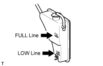 |
Check that the coolant level is between the FULL and LOW lines. If the coolant level is below the LOW line, repeat all of the procedures above. If the coolant level is above the FULL line, drain coolant so that the coolant level is between the FULL and LOW lines.
| 26. CONNECT CABLE TO NEGATIVE BATTERY TERMINAL |
| 27. INSPECT FOR COOLANT LEAK |
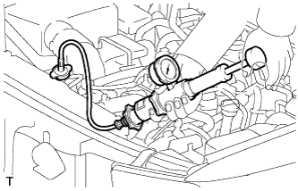 |
Fill the radiator with coolant and attach a radiator cap tester.
Warm up the engine.
Using the radiator cap tester, increase the pressure inside the radiator to 118 kPa (1.2 kgf/cm2, 17 psi), and check that the pressure does not drop. If the pressure drops, check the hoses, radiator and water pump for leaks. If no external leaks are found, check the heater core, cylinder block and head.
| 28. INSPECT IGNITION TIMING |
Warm up and stop the engine.
Allow the engine to warm up to a normal operating temperature.
When using the Techstream:
Connect the Techstream to the DLC3.
Start the engine and idle it.
Push the Techstream main switch ON.
Enter the following menus: Powertrain / Engine and ECT / Data List / Primary / IGN Advance.
Disconnect the Techstream from the DLC3.
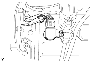 |
When not using the Techstream:
Connect the tester probe of a timing light to the wire of the ignition coil connector for the No. 1 cylinder.
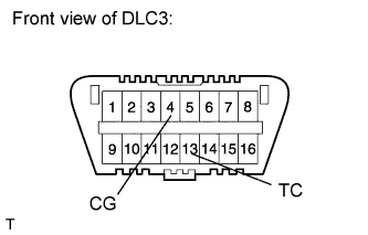 |
Using SST, connect terminals 13 (TC) and 4 (CG) of the DLC3.
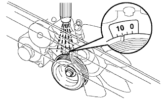 |
Using the timing light, check the ignition timing.
Remove SST from the DLC3.
Disconnect the timing light from the engine.
| 29. INSPECT ENGINE IDLE SPEED |
Warm up and stop the engine.
Allow the engine to warm up to a normal operating temperature.
When using the Techstream:
Connect the Techstream to the DLC3.
Race the engine at 2500 rpm for approximately 90 seconds.
Push the Techstream main switch ON.
Enter the following menus: Powertrain / Engine and ECT / Data List / Primary / Engine Speed.
Disconnect the Techstream from the DLC3.
 |
When not using the Techstream:
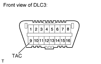
Using SST, connect the tachometer probe to terminal 9 (TAC) of the DLC3.
Race the engine at 2500 rpm for approximately 90 seconds.
Check the idle speed.
Disconnect the tachometer from the DLC3.
| 30. INSTALL NO. 1 ENGINE UNDER COVER |
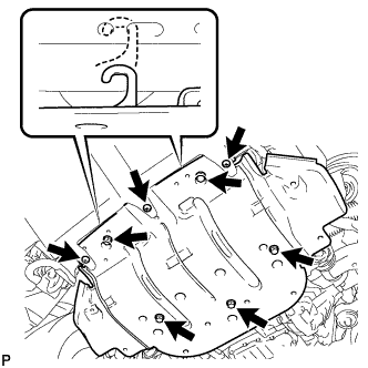 |
Hook the engine under cover onto the vehicle body as shown in the illustration.
Install the 3 screws and 5 bolts.