CYLINDER HEAD GASKET (for Bank 1) > INSTALLATION |
| 1. INSTALL CYLINDER HEAD GASKET |
Remove any old packing (FIPG) material and be careful not to drop any oil on the contact surfaces of the cylinder head and cylinder block.
![]() |
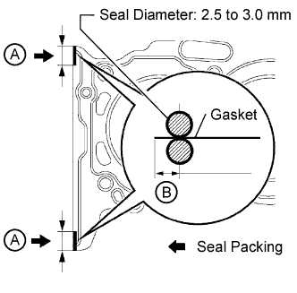
Apply seal packing to a new cylinder head gasket as shown in the illustration.
| A | 10 to 15 mm (0.394 to 0.591 in.) |
| B | 1.25 to 1.5 mm (0.0492 to 0.0591 in.) |
![]() |
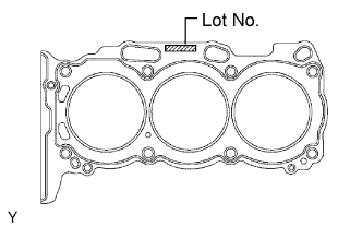
Place the cylinder head gasket on the cylinder block surface with the front face of the Lot No. stamp upward.
| 2. INSTALL CYLINDER HEAD SUB-ASSEMBLY RH |
Place the cylinder head on the cylinder head gasket.
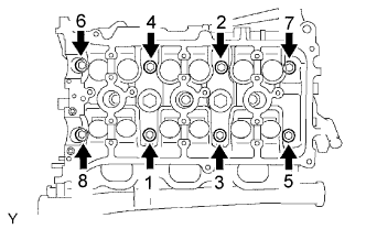
Install the 8 cylinder head bolts and plate washers.
Apply a light coat of engine oil to the threads and under the heads of the cylinder head bolts.
Install the plate washer to the cylinder head bolt.
Step 1:
![]() |
Using a 10 mm bi-hexagon wrench, install and uniformly tighten the 8 cylinder head bolts with the plate washers in several steps in the sequence shown in the illustration.
Step 2:
![]() |
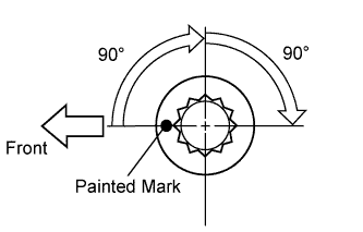
Mark the cylinder head bolt heads with paint as shown in the illustration.
Tighten the cylinder head bolts another 90° in the sequence shown in step 1.
Step 3:
Tighten the cylinder head bolts by an additional 90° in the sequence shown in step 1.
Check that the painted marks are now facing rearward.
![]() |
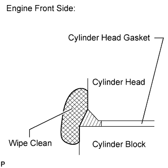
Seal packing will seep out from the engine's front side. Thoroughly wipe off seeped out seal packing.
| 3. INSTALL NO. 1 CAMSHAFT BEARING |
![]() |
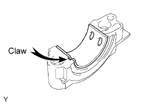
Align the bearing claw with the claw groove of the bearing cap, and push in the No. 1 camshaft bearing.
| 4. INSTALL NO. 2 CAMSHAFT BEARING |
![]() |
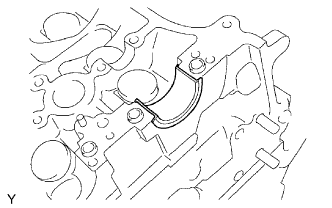
Install the No. 2 camshaft bearing to the cylinder head.
| 5. INSTALL NO. 1 CAMSHAFT AND NO. 2 CAMSHAFT |
![]() |
Set the crankshaft position.
Using the crankshaft pulley set bolt, turn the crankshaft, and set the crankshaft set key into the left horizontal position.
Apply a light coat of engine oil to the thrust portions and journals of the camshafts.
![]() |
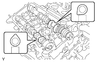
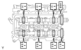
Place the 2 camshafts onto the cylinder head with the cam lobes of the No. 1 cylinder facing each direction as shown in the illustration.
Apply a light coat of engine oil to the 8 bearing caps.
![]() |
Install the 8 bearing caps in their proper locations.
Apply a light coat of engine oil to the threads and under the heads of the 16 bearing cap bolts.
![]() |
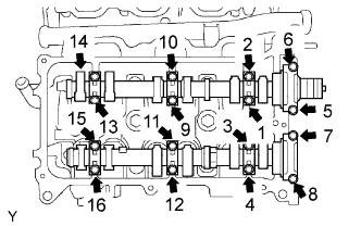
Uniformly install the 16 bearing cap bolts in several steps in the order shown in the illustration.
![]() |
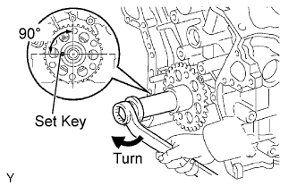
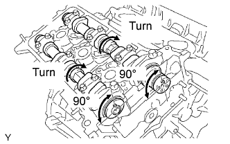
Using a wrench, turn the camshafts clockwise until the camshaft knock pin is at a position 90° to the cylinder head.
| 6. INSTALL NO. 2 CHAIN TENSIONER ASSEMBLY |
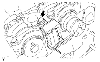
![]() |
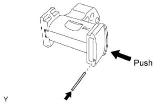
While pushing in the tensioner, insert a pin of φ 1.0 mm (0.0394 in.) into the hole to fix it.
![]() |
Install the No. 2 chain tensioner with the bolt.
| 7. INSTALL CAMSHAFT TIMING GEARS AND NO. 2 CHAIN |
![]() |
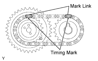
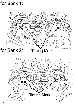
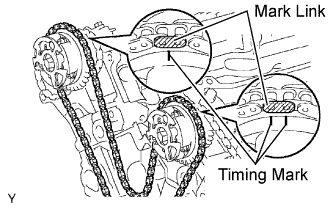
Align the mark links (yellow) of the No. 2 chain with the timing marks (1-dot mark) of the camshaft timing gear and sprocket as shown in the illustration.
![]() |
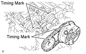
Align the timing marks on the camshaft timing gear and sprocket with the timing marks on the bearing caps, and install the camshaft timing gear and sprocket with the No. 2 chain to the camshafts.
Temporarily install the camshaft timing gear bolt and camshaft timing sprocket bolt.
![]() |
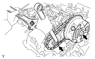
Hold the hexagonal portion of the camshaft with a wrench, and tighten the 2 bolts.
Remove the pin from the No. 2 chain tensioner.
| 8. INSTALL CHAIN TENSIONER SLIPPER |
| 9. INSTALL NO. 1 CHAIN TENSIONER ASSEMBLY |
![]() |
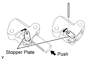
While turning the stopper plate of the tensioner clockwise, push in the plunger of the tensioner as shown in the illustration.
While turning the stopper plate of the tensioner counterclockwise, insert a bar of φ 3.5 mm (0.138 in.) into the holes on the stopper plate and tensioner to fix the stopper plate.
Install the chain tensioner with the 2 bolts.
| 10. INSTALL NO. 1 CHAIN |
![]() |
Set the No. 1 cylinder to TDC / compression.
Align the timing marks of the camshaft timing gears and sprockets with the timing marks of the bearing caps.
![]() |
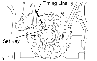
Install the crankshaft pulley set bolt, and turn the crankshaft to align the crankshaft set key with the timing line of the cylinder block.
![]() |
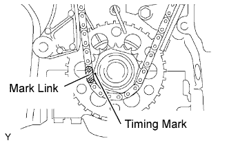
Align the mark link (yellow) with the timing mark of the crankshaft timing gear.
![]() |
Align the mark links (orange) with the timing marks of the camshaft timing gears, and install the No. 1 chain.
| 11. INSTALL NO. 2 CHAIN VIBRATION DAMPER |
![]() |
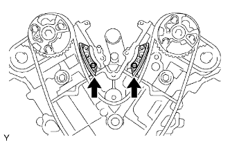
Install the 2 No. 2 chain vibration dampers.
| 12. INSTALL NO. 1 IDLE GEAR SHAFT |
Apply a light coat of engine oil to the rotating surface of the No. 1 idle gear shaft.
![]() |
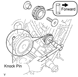
Temporarily install the No. 1 idle gear shaft and No. 1 idle gear with the No. 2 idle gear shaft while aligning the knock pin of the No. 1 idle gear shaft with the knock pin groove of the cylinder block.
Using a 10 mm hexagon wrench, tighten the No. 2 idle gear shaft.
Remove the bar from the chain tensioner.
| 13. INSTALL FRONT CRANKSHAFT OIL SEAL |
![]() |
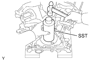
Using SST and a hammer, tap in a new oil seal until its surface is flush with the timing chain cover edge.
Apply MP grease to the oil seal lip.
| 14. INSTALL TIMING CHAIN COVER SUB-ASSEMBLY |
Remove any old packing (FIPG) material and be careful not to drop any oil on the contact surfaces of the timing chain cover, cylinder head and cylinder block.
![]() |
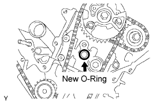
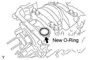
Install a new O-ring to the cylinder head for bank 2 shown in the illustration.
![]() |
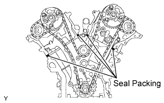
Apply seal packing as shown in the illustration.
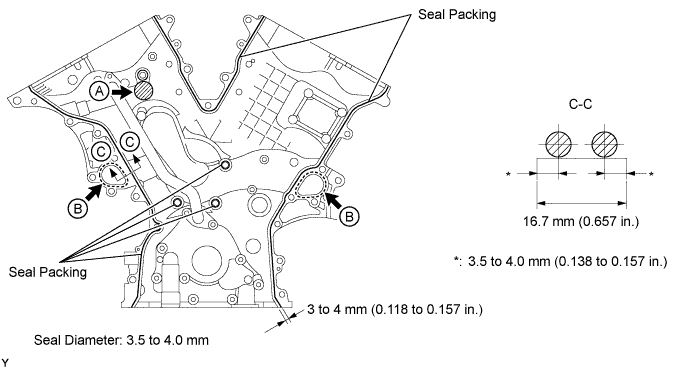
Apply seal packing in a continuous line to the timing chain cover as shown in the illustration.

![]() |
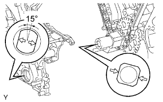
Align the key way of the oil pump drive rotor with the rectangular portion of the crankshaft timing gear, and slide the timing chain cover into place.
![]() |
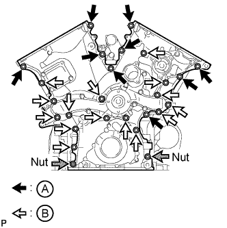
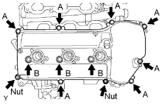
Install the timing chain cover with the 24 bolts labeled A and B, and 2 nuts. Tighten the bolts and nuts uniformly in several steps.
| Item | Quantity | Length |
| A | 9 | 25 mm (0.984 in.) |
| B | 15 | 55 mm (2.17 in.) |
| 15. INSTALL OIL FILTER BRACKET SUB-ASSEMBLY |
Set a new O-ring to the timing chain cover.
![]() |
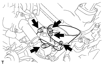
Install the oil filter bracket with the 3 bolts and 2 nuts.
| 16. INSTALL WATER INLET HOUSING |
![]() |
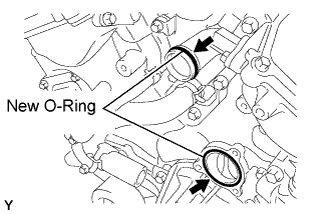
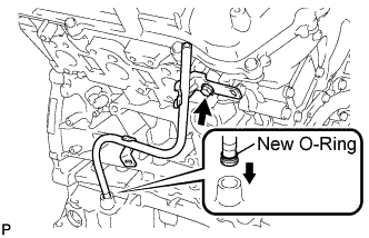
Apply soapy water to a new O-ring, install it to the water outlet pipe.
Install a new O-ring to the water pump.
Install a new gasket to the water pump.
![]() |
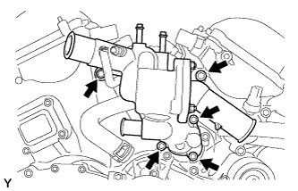
Install the water inlet with the 5 bolts.
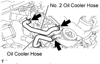
| 17. CONNECT OIL COOLER HOSE |
![]() |
| 18. CONNECT NO. 2 OIL COOLER HOSE |
| 19. INSTALL OIL PAN SUB-ASSEMBLY |
Remove any old packing (FIPG) material and be careful not to drop any oil on the contact surfaces of the cylinder block, rear oil seal retainer and oil pan.
![]() |
Install a new O-ring to the oil pan.
![]() |
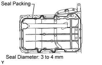
Apply seal packing in a continuous line as shown in the illustration.
![]() |
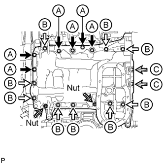
Install the oil pan with the 17 bolts (A, B and C) and 2 nuts. Tighten the bolts and nuts uniformly in several steps.
| Item | Quantity | Length |
| A | 6 | 25 mm (0.984 in.) |
| B | 9 | 45 mm (1.77 in.) |
| C | 2 | 14 mm (0.551 in.) |
| 20. INSTALL OIL STRAINER SUB-ASSEMBLY |
![]() |
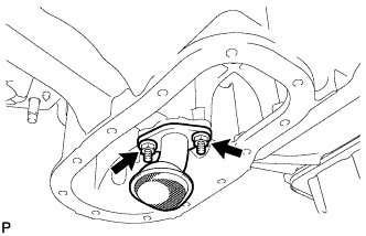
Install a new gasket and the oil strainer with the 2 nuts.
| 21. INSTALL NO. 2 OIL PAN SUB-ASSEMBLY |
![]() |
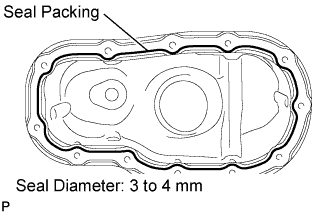
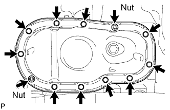
Apply seal packing in a continuous line as shown in the illustration.
![]() |
Install the No. 2 oil pan with the 10 bolts and 2 nuts. Tighten the bolts and nuts uniformly in several steps.
| 22. INSTALL CYLINDER HEAD COVER SUB-ASSEMBLY RH |
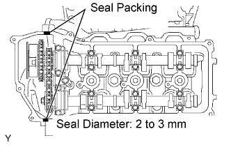
Remove any old packing (FIPG) material and be careful not to drop any oil on the contact surfaces of the cylinder head, timing chain cover and cylinder head cover.
![]() |
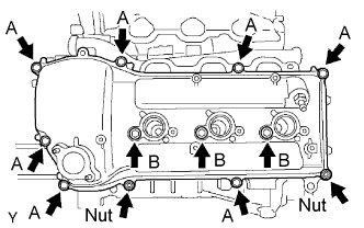
Apply seal packing as shown in the illustration.
Install a new gasket to the cylinder head cover.
Install the seal washers to the bolts.
![]() |
Temporarily install the cylinder head cover with the 10 bolts and 2 nuts. Tighten the bolts and nuts uniformly in several steps.
| 23. INSTALL CYLINDER HEAD COVER SUB-ASSEMBLY LH |
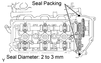
Remove any old packing (FIPG) material and be careful not to drop any oil on the contact surfaces of the cylinder head, timing chain cover and cylinder head cover.
![]() |
Apply seal packing as shown in the illustration.
Install a new gasket to the cylinder head cover.
Install the seal washers to the bolts.
![]() |
Temporarily install the cylinder head cover with the 10 bolts and 2 nuts. Tighten the bolts and nuts uniformly in several steps.
| 24. INSTALL ENGINE OIL LEVEL DIPSTICK GUIDE |
![]() |
Install a new O-ring to the dipstick guide.
Apply a light coat of engine oil to the O-ring.
Push the dipstick guide end into the guide hole.
Install the dipstick guide with the bolt.
| 25. INSTALL REAR WATER BY-PASS JOINT |
![]() |
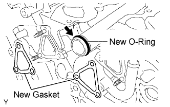
Install a new O-ring to the water outlet pipe, and set 2 new gaskets to the water ports LH and RH.
Apply soapy water to the O-ring.
![]() |
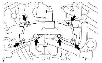
Install the rear water by-pass joint with the 2 bolts and 4 nuts.
Connect the engine coolant temperature sensor connector.
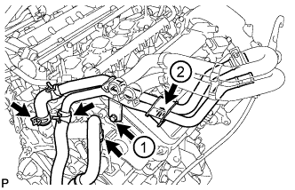
| 26. INSTALL HEATER WATER PIPE SUB-ASSEMBLY |
![]() |
Temporarily install the heater water pipe, and then tighten the 2 bolts in the order shown in the illustration.
Connect the 3 water hoses.
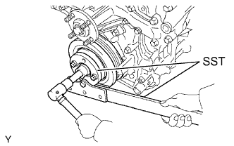
| 27. INSTALL CRANKSHAFT PULLEY |
![]() |
Using SST, install the pulley set bolt.
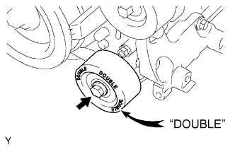
| 28. INSTALL NO. 1 IDLER PULLEY SUB-ASSEMBLY |
![]() |
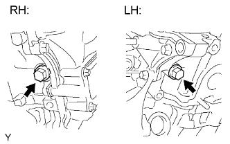
Install the No. 1 idler pulley with the bolt.
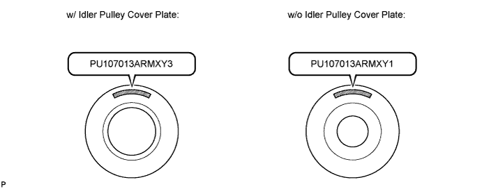
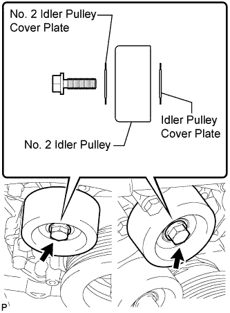
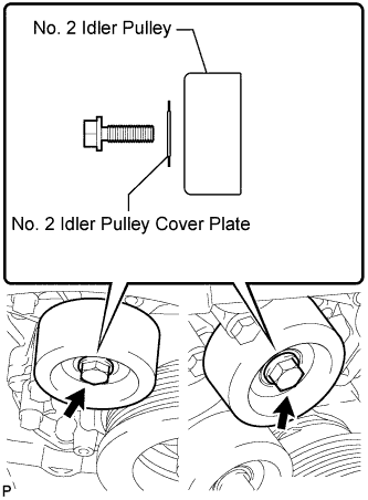
| 29. INSTALL NO. 2 IDLER PULLEY SUB-ASSEMBLY |

w/ Idler Pulley Cover Plate (PU107013ARMXY3):
![]() |
Install the idler pulley cover plate, idler pulley and No. 2 idler pulley cover plate with the bolt.
w/o Idler Pulley Cover Plate (PU107013ARMXY1):
![]() |
Install the idler pulley and No. 2 idler pulley cover plate with the bolt.
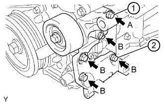
| 30. INSTALL V-RIBBED BELT TENSIONER ASSEMBLY |
![]() |
Temporarily install the V-ribbed belt tensioner with the 5 bolts.
Install the V-ribbed belt tensioner by tightening bolt 1 and 2 in numerical order.
Tighten the other bolts.
| Item | Length |
| A | 70 mm (2.76 in.) |
| B | 33 mm (1.30 in.) |
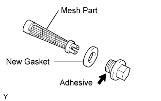
| 31. INSTALL OIL CONTROL VALVE FILTER |
![]() |
Install 2 new gaskets to 2 new unions.
Insert new filters to the unions.
Apply adhesive to 2 or 3 threads of the unions.
![]() |
Install the unions to each cylinder head.
| 32. CONNECT HEATER WATER PIPE SUB-ASSEMBLY |
Connect the heater water by-pass pipe's hose to the rear water by-pass joint.
![]() |
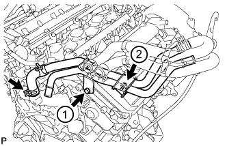
Temporarily install the heater water pipe, and then tighten the 2 bolts in the order shown in the illustration.
| 33. INSTALL SPARK PLUG |
Using a 16 mm plug wrench, install the 6 spark plugs.
| 34. INSTALL VVT SENSOR |
![]() |
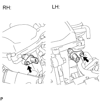
Apply a light coat of engine oil to the O-ring of each VVT sensor.
Install the 2 VVT sensors with the 2 bolts.
| 35. INSTALL CAMSHAFT TIMING OIL CONTROL VALVE ASSEMBLY |
![]() |
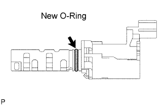
Apply a light coat of engine oil to a new O-ring of the camshaft timing oil control valve and install the O-ring.
![]() |
Install the camshaft timing oil control valve with the bolt.
| 36. INSTALL IGNITION COIL ASSEMBLY |
![]() |
Install the 6 ignition coils with the 6 bolts.
Connect the 6 ignition coil connectors.
| 37. INSTALL ENGINE ASSEMBLY |
Install the engine assembly to the vehicle (Click here).