 |
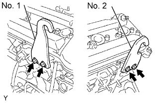
Install the 2 engine hangers with the 4 bolts shown in the illustration.
| Item | Part No. |
| No. 1 engine hanger | 12281-31060 |
| No. 2 engine hanger | 12282-31040 |
| Bolt | 90119-08A87 |
- Torque:
- 33 N*m{ 336 kgf*cm , 24 ft.*lbf }
ENGINE ASSEMBLY > INSTALLATION |
| 1. INSTALL ENGINE HANGER |
|
Install the 2 engine hangers with the 4 bolts shown in the illustration.
| Item | Part No. |
| No. 1 engine hanger | 12281-31060 |
| No. 2 engine hanger | 12282-31040 |
| Bolt | 90119-08A87 |
| 2. REMOVE ENGINE STAND |
Attach an engine sling device and hang the engine with a chain block.
Lift the engine, and remove it from the engine stand.
Place the engine onto a working bench.
| 3. INSTALL DRIVE PLATE AND RING GEAR |
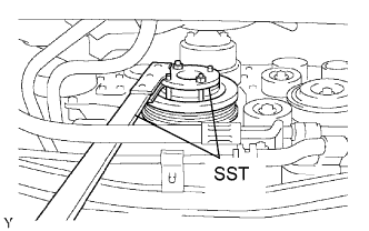 |
Using SST, hold the crankshaft.
Temporarily install the front spacer, drive plate and rear spacer with the 8 bolts.
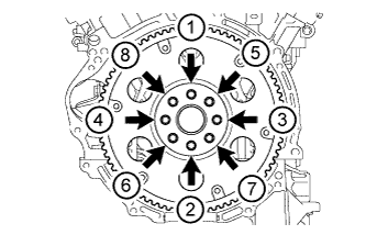 |
Tighten the 8 bolts uniformly in several steps in the order shown in the illustration.
| 4. INSTALL ENGINE ASSEMBLY |
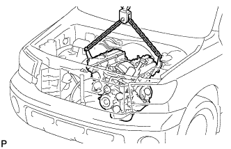 |
Attach the engine sling device and hang the engine with the chain block.
Slowly lower the engine into the engine compartment.
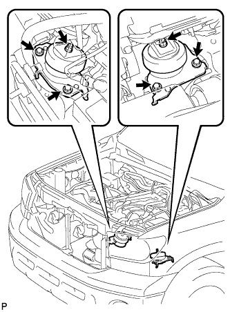 |
Install the front engine mounting insulator LH.
Install the front engine mounting insulator RH.
Remove the 2 engine hangers and 4 bolts.
| 5. INSTALL AUTOMATIC TRANSMISSION ASSEMBLY |
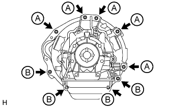 |
Install the transmission with the 9 bolts.
| 6. CONNECT NO. 1 WATER BY-PASS PIPE |
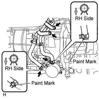 |
Connect the 2 water by-pass hoses with the 2 clips and install the water by-pass pipe with the 2 bolts.
| 7. CONNECT WIRE HARNESS AND CONNECTOR |
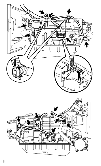 |
Connect the park/neutral start switch connector, transmission wire connector and 2 speed sensor connectors.
Connect the harness clamp with the bolt.
Connect the 4 connector clamps and 4 harness clamps.
Tilt up the automatic transmission.
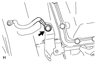 |
Connect the ground cable with the bolt.
| 8. INSTALL REAR NO. 1 ENGINE MOUNTING INSULATOR |
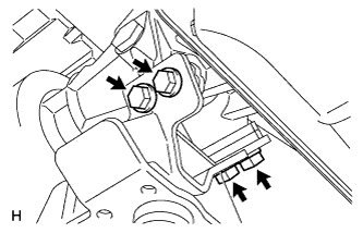 |
Install the engine mounting insulator to the transmission with the 4 bolts.
| 9. INSTALL NO. 3 FRAME CROSSMEMBER SUB-ASSEMBLY |
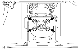 |
Install the frame crossmember to the engine rear mounting insulator with the 4 bolts.
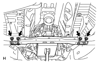 |
Install the frame crossmember with the 4 bolts, 4 plate washers and 4 nuts.
| 10. INSTALL FLYWHEEL HOUSING UNDER COVER |
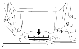 |
Install the flywheel housing under cover.
| 11. INSTALL DRIVE PLATE AND TORQUE CONVERTER CLUTCH SETTING BOLT |
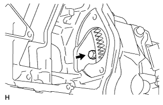 |
Turn the crankshaft to gain access to the 6 bolts and install each bolt while holding the crankshaft pulley setting bolt with a wrench.
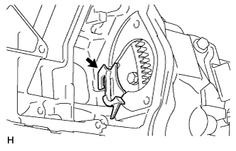 |
Install the flywheel housing side cover.
| 12. INSTALL STARTER ASSEMBLY |
Install the starter (for 1.6 kW Type) .
Install the starter (for 2.0 kW Type) .
| 13. INSTALL FRONT FENDER APRON SEAL RH |
| 14. INSTALL FRONT FENDER APRON SEAL LH |
| 15. INSTALL BATTERY |
| 16. CONNECT NO. 1 AND NO. 2 FUEL PIPE |
Check that there is no damage or contamination in the connected part of pipe.
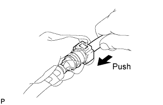 |
Align the axis of the connector with the axis of the pipe. Push the pipe into the connector until the connector makes a "click" sound. If the connection is tight, apply a small amount of fresh engine oil on the tip of the pipe.
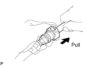 |
After having finished the connection, try to pull apart the pipe and the connector and confirm that they are securely connected.
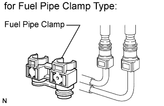 |
Install the fuel pipe clamp to the connector.
| 17. INSTALL COOLER COMPRESSOR |
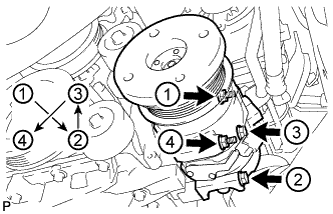 |
Install the cooler compressor with the 2 nuts and 2 bolts in several steps in the sequence shown in the illustration.
Connect the cooler compressor connector.
| 18. INSTALL GENERATOR ASSEMBLY |
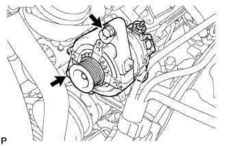 |
Install the generator with the 2 bolts.
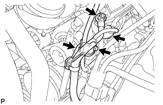 |
Install the wire harness clamp bracket with the bolt.
Install the wire harness clamp to the bracket.
Connect the generator wire with the nut.
Install the terminal cap.
Connect the generator connector.
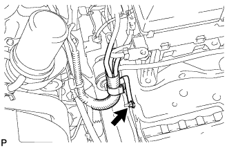 |
Install the wire harness clamp bracket with the nut.
| 19. CONNECT VANE PUMP ASSEMBLY |
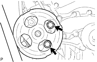 |
Install the vane pump with the 2 bolts.
| 20. CONNECT HEATER WATER INLET HOSE |
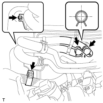 |
Install the heater water pipe bracket with the nut.
Connect the heater water inlet and outlet hose.
Connect the wire harness clamp.
| 21. INSTALL RADIATOR ASSEMBLY |
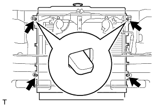 |
Set the radiator bracket hooks to the radiator support holes.
Install the radiator with the 4 bolts.
| 22. INSTALL RADIATOR SIDE DEFLECTOR RH |
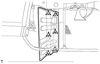 |
Install the deflector with the 6 clips.
| 23. INSTALL RADIATOR SIDE DEFLECTOR LH |
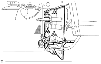 |
Install the deflector with the 6 clips.
Install the wire harness clamp.
| 24. INSTALL FAN SHROUD |
Install the fan pulley to the water pump.
Place the shroud together with the coupling fan between the radiator and engine.
Install the fluid coupling fan to the water pump with the 4 nuts. Tighten the nuts as much as possible by hand.
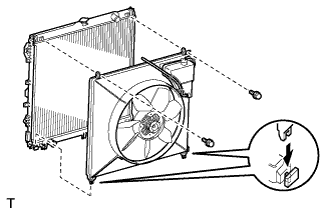 |
Attach the shroud's claws to the radiator as shown in the illustration.
Install the shroud with the 2 bolts.
Connect the reservoir hose to the radiator tank upper.
Install the fan and generator V-belt (Click here).
Tighten the 4 nuts of the fluid coupling fan.
| 25. CONNECT RADIATOR HOSE OUTLET |
| 26. CONNECT RADIATOR HOSE INLET |
| 27. INSTALL EXHAUST MANIFOLD SUB-ASSEMBLY LH |
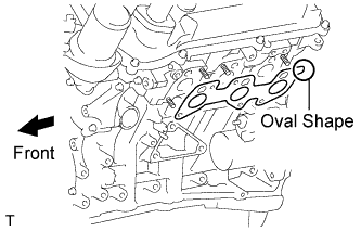 |
Set a new gasket to the cylinder head LH with the oval shape facing backward.
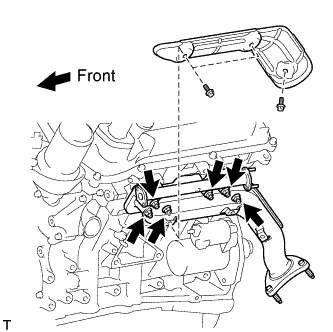 |
Install the exhaust manifold with 6 new nuts.
| 28. INSTALL NO. 2 EXHAUST MANIFOLD HEAT INSULATOR |
Install the heat insulator with the 3 bolts.
| 29. INSTALL EXHAUST MANIFOLD SUB-ASSEMBLY RH |
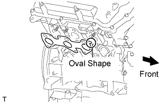 |
Set a new gasket to the cylinder head RH with the oval shape facing forward.
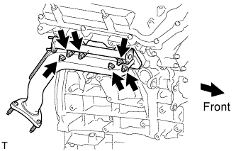 |
Install the exhaust manifold with 6 new nuts.
| 30. INSTALL FRONT EXHAUST PIPE ASSEMBLY |
Install a new gasket and the front exhaust pipe to the exhaust manifold RH with 3 new nuts.
Connect the air fuel ratio sensor connector.
Connect the heated oxygen sensor connector.
Attach the 2 heated oxygen sensor wire clamps.
| 31. INSTALL FRONT NO. 2 EXHAUST PIPE ASSEMBLY (except Regular Cab Standard Deck) |
| 32. INSTALL FRONT NO. 2 EXHAUST PIPE ASSEMBLY (for Regular Cab Standard Deck) |
| 33. INSTALL FRONT NO. 3 EXHAUST PIPE SUB-ASSEMBLY (for Regular Cab Standard Deck) |
Install a new gasket to the front No. 2 exhaust pipe.
Connect the front No. 3 exhaust pipe to the exhaust pipe support.
Install the front No. 3 exhaust pipe with the 2 bolts and 2 new nuts.
| 34. INSTALL AIR SWITCHING VALVE ASSEMBLY |
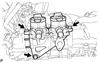 |
Install the air switching valve with the bolt and 2 nuts.
| 35. INSTALL NO. 2 AIR TUBE |
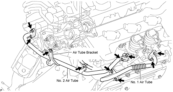
Connect the No. 2 air tube.
Temporarily install a new gasket and the No. 2 air tube to the air switching valve side with the 2 nuts. Then temporarily install a new gasket and the No. 2 air tube to the exhaust manifold side with the 2 nuts.
Temporarily install the No. 2 air tube bracket to the rear water by-pass joint with the bolt.
Tighten the bolt and 4 nuts.
Connect the wire harness clamp.
| 36. INSTALL NO. 1 AIR TUBE |
Install the No. 1 air tube.
Temporarily install a new gasket and the No. 1 air tube to the exhaust manifold side with the 2 nuts.
Install a new gasket and the No. 1 air tube to the air switching valve side with the 2 bolts.
Tighten the 2 nuts on the exhaust manifold side.
| 37. CONNECT NO. 4 AIR INJECTION SYSTEM HOSE |
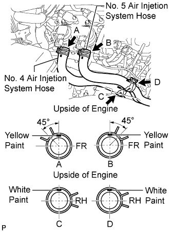 |
Install the air injection system hose and the 2 clamps as shown in the illustration.
| 38. CONNECT NO. 5 AIR INJECTION SYSTEM HOSE |
Install the air injection system hose and the 2 clamps as shown in the illustration.
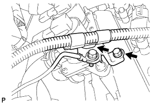 |
Connect the wire harness bracket with the bolt and attach the wire harness clamp.
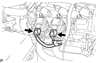 |
Connect the 2 air pump connectors.
| 39. CONNECT ENGINE WIRE |
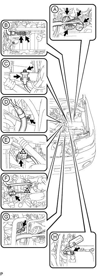 |
Engine Room LH Side:
Install the battery positive cable with the nut labeled H shown in the illustration.
Connect the battery positive cable cover.
Install the ground cable with the bolt labeled G shown in the illustration.
Attach the wire harness clamp to the front engine mounting bracket LH, and connect the connector to the crankshaft position sensor labeled F shown in the illustration.
Attach the front ABS junction connector's clamp to the engine room relay block side, and connect the connector labeled E shown in the illustration.
Connect the wire harness bracket with the nut labeled D shown in the illustration.
Connect the No. 2 engine wire's cover to the engine room relay block, and install the No. 2 engine wire with the nut labeled C shown in the illustration.
Connect the 2 connectors to the engine room relay block labeled B shown in the illustration.
Connect the 4 connectors to the air injection control driver labeled A shown in the illustration.
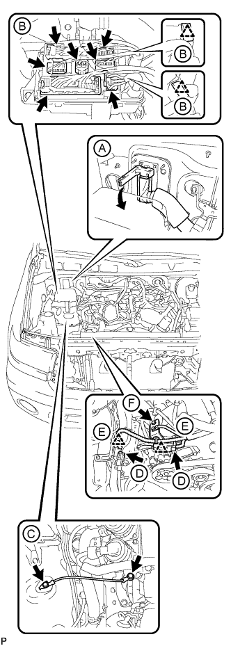 |
Engine Room RH Side:
Install the bracket with the bolt labeled F shown in the illustration.
Attach the 2 wire harness clamps labeled E shown in the illustration.
Connect the 2 air pump connectors labeled D shown in the illustration.
Install the ground cable with the 2 bolts labeled C shown in the illustration.
Attach the 2 wire harness clamps labeled B shown in the illustration.
Connect the 7 connectors to the junction block labeled B shown in the illustration.
Install the junction block cover.
Connect the ECM connector labeled A shown in the illustration.
| 40. INSTALL INTAKE AIR SURGE TANK |
Install a new gasket to the intake air surge tank.
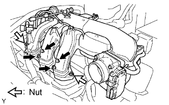 |
Using an 8 mm hexagon wrench, install the intake air surge tank with the 4 bolts and 2 nuts.
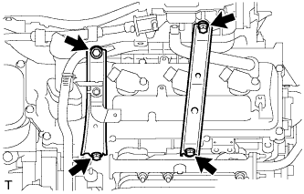 |
Install the No. 2 surge tank stay with the 2 bolts.
Install the No. 1 surge tank stay with the 2 bolts.
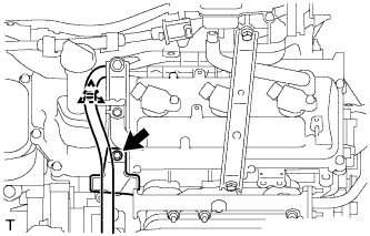 |
Install the oil baffle plate with the bolt.
Attach the wire harness clamp.
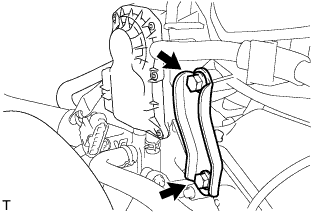 |
Install the throttle body bracket with the 2 bolts.
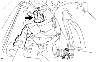 |
Connect the vacuum switching valve (for ACIS) connector.
Attach the 2 wire harness clamps.
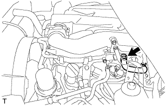 |
Connect the No. 1 ventilation hose.
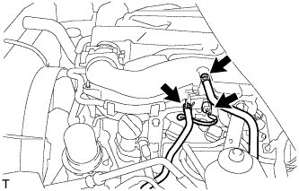 |
Connect the union to check valve hose.
Connect the purge VSV connector.
Connect the purge line hose.
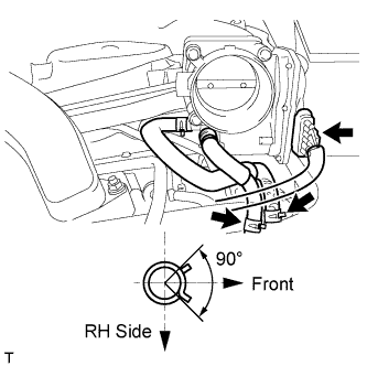 |
Connect the No. 4 water by-pass hose.
Connect the No. 5 water by-pass hose.
Connect the throttle position sensor and throttle control motor connector.
| 41. INSTALL AIR CLEANER ASSEMBLY |
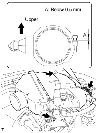 |
Install the air cleaner with element with the 2 bolts.
Tighten the hose clamp.
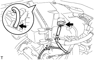 |
Connect the MAF meter connector.
Attach the 2 wire harness clamps.
Connect the vacuum hose.
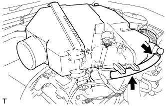 |
Attach the hose clamp.
Connect the No. 2 ventilation hose.
| 42. INSTALL NO. 2 AIR CLEANER HOSE |
 |
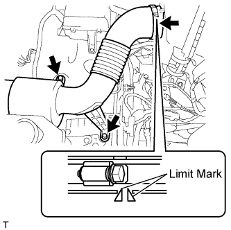 |
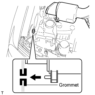
Install the air cleaner hose with the 2 bolts.
Tighten the hose clamp.
| 43. INSTALL FRONT COWL TOP OUTER PANEL SUB-ASSEMBLY |
Install the front cowl top outer panel with the 7 bolts.
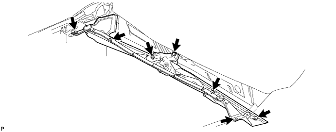
Connect the 2 washer hoses.
| 44. INSTALL FRONT WIPER MOTOR AND LINK |
Install the front wiper motor and link (Click here).
| 45. CONNECT CABLE TO NEGATIVE BATTERY TERMINAL |
| 46. ADD ENGINE OIL |
Remove the oil filler cap.
Add new oil.
| Oil grade | Oil Viscosity (SAE) |
| ILSAC multigrade engine oil | 5W-30 (5W-30 is the best choice for good fuel economy and good starting in cold weather.) |
| Item | Specified Condition |
| Drain and refill with oil filter change | 5.2 liters (5.5 US qts, 4.6 Imp. qts) |
| Drain and refill without oil filter change | 4.9 liters (5.2 US qts, 4.3 Imp. qts) |
| Dry fill | 6.0 liters (6.3 US qts, 5.3 Imp. qts) |
Install the oil filler cap.
| 47. INSPECT FOR FUEL LEAK |
Connect the Techstream to the DLC3.
Turn the ignition switch to ON and Techstream main switch ON.
Enter the following menus: Powertrain / Engine and ECT / Active Test / Control the Fuel Pump / Speed.
Check that there are no fuel leaks after doing maintenance anywhere on the fuel system.
| 48. ADD AUTOMATIC TRANSMISSION FLUID |
Add automatic transmission fluid (Click here).
| 49. ADD ENGINE COOLANT |
Add engine coolant.
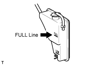 |
Slowly pour coolant into the radiator reservoir until it reaches the FULL line.
Install the reservoir cap.
Press the inlet and outlet radiator hoses several times by hand, and then check the coolant level. If the coolant level is low, add coolant.
Install the radiator cap.
Start the engine and warm it up until the thermostat opens.
Maintain the engine speed at 2000 to 2500 rpm.
Press the inlet and outlet radiator hoses several times by hand to bleed air.
Stop the engine, and wait until the engine coolant cools down to ambient temperature.
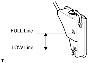 |
Check that the coolant level is between the FULL and LOW lines.
If the coolant level is below the LOW line, repeat all of the procedures above.
If the coolant level is above the FULL line, drain coolant so that the coolant level is between the FULL and LOW lines.
| 50. INSPECT FOR COOLANT LEAK |
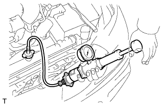 |
Fill the radiator with coolant and attach a radiator cap tester.
Warm up the engine.
Using the radiator cap tester, increase the pressure inside the radiator to 118 kPa (1.2 kgf/cm2, 17 psi), and check that the pressure does not drop.
If the pressure drops, check the hoses, radiator and water pump for leaks. If no external leaks are found, check the heater core, cylinder block and head.
| 51. ADJUST SHIFT LEVER POSITION |
Move the shift lever to the N position.
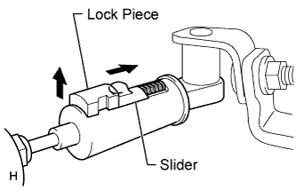 |
Fold back the transmission control cable adjust case cover. Then while sliding the slider toward the cable end side, press the lock piece from the back side to release the lock.
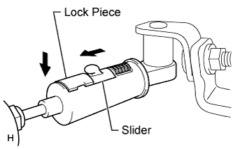 |
Check that the adjust case's spring is applying enough tension to the shift control cable. Then press the lock piece to set the lock.
Return the cover of the adjust case to its original position.
Inspect the operation after the adjustment.
| 52. INSPECT SHIFT LEVER POSITION |
When moving the shift lever from the N position to other positions, check that the lever can be shifted smoothly and accurately to each position and that the position indicator comes on in accordance with the shift lever position.
If the indicator and shift lever position do not match, carry out the following adjustment procedures.
| 53. INSPECT FOR OIL LEAK |
| 54. INSPECT FOR EXHAUST GAS LEAK |
| 55. CHECK ENGINE OIL LEVEL |
Warm up the engine, stop the engine and wait 5 minutes. The oil level should be between the dipstick's low and full level marks.
If the oil level is low, check for leakage and add oil up to the full level mark.
| 56. PERFORM RESET MEMORY |
Perform the RESET MEMORY procedures (A/T initialization) (Click here).
| 57. INSPECT IGNITION TIMING |
Warm up the engine.
When using the Techstream:
Connect the Techstream to the DLC3.
Enter the following menus:
Select: Powertrain / Engine and ECT / Data List / All Data / IGN Advance
Inspect the ignition timing during idling.
Check that the ignition timing advances immediately when the engine speed is increased.
 |
When not using Techstream:
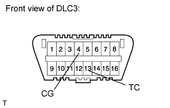
Using SST, connect terminals 13 (TC) and 4 (CG) of the DLC3.
Remove the air cleaner cap.
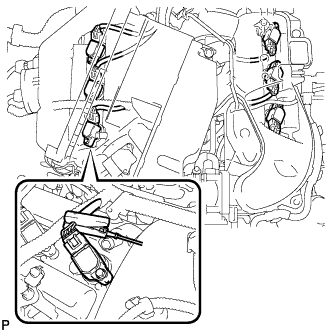 |
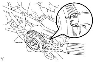
Pull out the wire harness as shown in the illustration.
Connect the tester probe of a timing light to the wire of the ignition coil connector for the No. 1 cylinder.
 |
Inspect the ignition timing during idling.
Remove SST from the DLC3.
Inspect the ignition timing during idling.
Disconnect the timing light from the engine.
Install the air cleaner cap.
| 58. INSPECT ENGINE IDLE SPEED |
Warm up the engine.
When using the Techstream:
Connect the Techstream to the DLC3.
Enter the following menus:
Select: Powertrain / Engine and ECT / Data List / All Data / Engine Speed
Inspect the engine idling speed.
 |
When not using the Techstream:
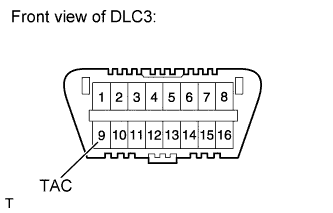
Using SST, connect terminal 9 (TAC) of the DLC3.
Race the engine at 2500 rpm for approximately 90 seconds.
Inspect the engine idling speed.
| 59. INSPECT CO/HC |
Start the engine.
Run the engine at 2500 rpm for approximately 180 seconds.
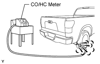 |
Insert the CO/HC meter testing probe at least 40 cm (1.31 ft) into the tailpipe during idling.
Immediately check the CO/HC concentration during idling and/or at 2500 rpm.
If the CO/HC concentration does not comply with regulations, perform troubleshooting in the order given below.
Check the A/F sensor operation (Click here) and heated oxygen sensor operation (Click here).
See the table below for possible causes, and then inspect and correct the corresponding causes if necessary.
| CO | HC | Symptom | Causes |
| Normal | High | Rough idling |
|
| Low | High | Rough idling (Fluctuating HC reading) |
|
| High | High | Rough idle (Black smoke from exhaust) |
|
| 60. INSTALL V-BANK COVER |
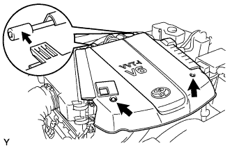 |
Install the V-bank cover with the 2 nuts.
| 61. INSTALL NO. 1 ENGINE UNDER COVER |
Install the engine under cover with the 5 bolts and 3 screws.
| 62. INSTALL HOOD SUB-ASSEMBLY |
Install the hood with the 4 bolts.
| 63. CONNECT HOOD SUPPORT ASSEMBLY |
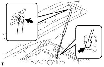 |
Install the hood support assembly.
| 64. ADJUST HOOD SUB-ASSEMBLY |
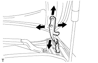 |
Adjust the hood's position.
Loosen the hood's 4 hinge bolts.
Move the hood and adjust the clearance between the hood and front fender.
Tighten the hood's 4 hinge bolts after the adjustment.
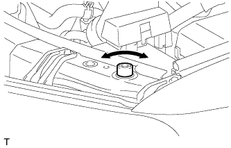 |
Adjust the cushion rubber so that the height of the hood and fender are aligned.
Adjust the hood lock.
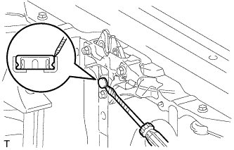 |
Using a screwdriver, remove the hood lock nut cap as shown in the illustration.
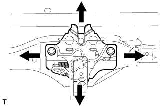 |
Loosen the 2 bolts and hood lock nut.
Adjust the hood lock position so that the striker can enter it smoothly.
Tighten the bolts and nut after the adjustment.
Install a new cap.
| 65. INSPECT COOLANT LEVEL AT RESERVOIR |
|
Check that the engine coolant level is between the LOW and FULL lines when the engine is cold.
If the engine coolant is low, check for leaks and add "TOYOTA Super Long Life Coolant" or similar high quality ethylene glycol based non-silicate, non-amine, non-nitrite and non-borate coolant with long-life hybrid organic acid technology to the FULL line.
| 66. INSPECT FOR LEAKAGE OF REFRIGERANT |
After recharging the refrigerant gas, check for refrigerant gas leakage using a halogen leak detector.
Perform the operation under the following conditions:
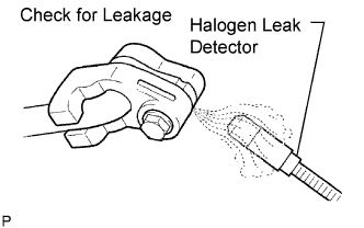 |
Using a halogen leak detector, check the refrigerant line for leakage.
If a gas leak is not detected on the drain hose, remove the blower motor control (blower resistor) from the cooling unit. Insert the halogen leak detector sensor into the unit and perform the test.
Disconnect the connector and wait for approximately 20 minutes. Bring the halogen leak detector close to the pressure switch and perform the test.