Home › ENGINE · 1GR-FE › ENGINE MECHANICAL › CAMSHAFT (for Bank 1)

CAMSHAFT (for Bank 1) > INSTALLATION

for Preparation Click here


1. INSTALL NO. 1 CAMSHAFT AND NO. 2 CAMSHAFT

NOTICE:
As the thrust clearance of the camshaft is small, the camshaft must be kept level while it is being installed. If the camshaft is not kept level, the portion of the cylinder head which receives the shaft thrust may crack or be damaged, causing the camshaft to seize or break. To avoid this, the following steps should be carried out.


    A076280E02
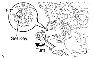
  1. Set the crankshaft position.

    1. Using the crankshaft pulley set bolt, turn the crankshaft, and set the crankshaft set key into the left horizontal position.

      NOTICE:
      Having the crankshaft at the wrong angle can cause the piston head and valve head to come into contact with each other when the camshaft is installed, causing damage. Always set the crankshaft at the correct angle.
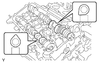
  1. Apply a light coat of engine oil to the thrust portions and journals of the camshafts.


    A076281E06
  1. Place the 2 camshafts onto the cylinder head with the cam lobes of the No. 1 cylinder facing each direction as shown in the illustration.

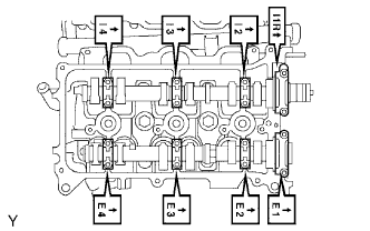
  1. Apply a light coat of engine oil to the 8 bearing caps.


    A076282E06
  1. Install the 8 bearing caps in their proper locations.

  1. Apply a light coat of engine oil to the threads and under the heads of the 16 bearing cap bolts.


    A072967E18
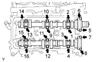
  1. Uniformly install the 16 bearing cap bolts in several steps in the order shown in the illustration.

    Torque:
    for 10 mm head:
    9.0 N*m{ 92 kgf*cm , 80 in.*lbf }
    for 12 mm head:
    24 N*m{ 245 kgf*cm , 18 ft.*lbf }


    A076283E09
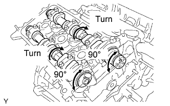
  1. Using a wrench, turn the camshafts clockwise until the camshaft knock pin is at a position 90° to the cylinder head.


2. INSTALL NO. 2 CHAIN TENSIONER ASSEMBLY


    A076286E01
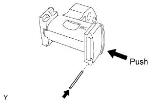
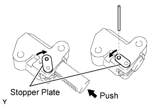
  1. While pushing in the tensioner, insert a pin of φ 1.0 mm (0.0394 in.) into the hole to fix it.


    A072962E02
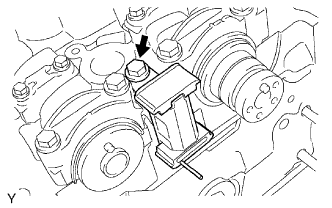
  1. Install the No. 2 chain tensioner with the bolt.

    Torque:
    21 N*m{ 214 kgf*cm , 15 ft.*lbf }


3. INSTALL CAMSHAFT TIMING GEARS AND NO. 2 CHAIN


    A076287E05
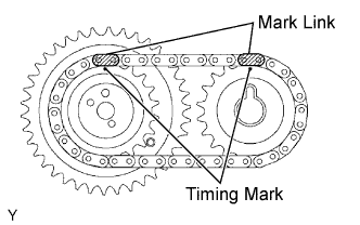
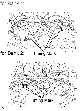
  1. Align the mark links (yellow) of the No. 2 chain with the timing marks (1-dot mark) of the camshaft timing gear and sprocket as shown in the illustration.


    G038109E02
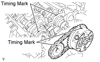
  1. Align the timing marks on the camshaft timing gear and sprocket with the timing marks on the bearing caps, and install the camshaft timing gear and sprocket with the No. 2 chain to the camshafts.

  1. Temporarily install the camshaft timing gear bolt and camshaft timing sprocket bolt.

    NOTICE:
    Do not push the camshaft timing gear assembly to the camshaft forcibly when installing it.


    G038110E01
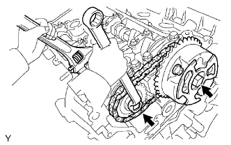
  1. Hold the hexagonal portion of the camshaft with a wrench, and tighten the 2 bolts.

    Torque:
    100 N*m{ 1020 kgf*cm , 74 ft.*lbf }

  1. Remove the pin from the No. 2 chain tensioner.


4. INSTALL CHAIN TENSIONER SLIPPER


5. INSTALL NO. 1 CHAIN TENSIONER ASSEMBLY


    A158631E01
  1. While turning the stopper plate of the tensioner clockwise, push in the plunger of the tensioner as shown in the illustration.

  1. While turning the stopper plate of the tensioner counterclockwise, insert a bar of φ 3.5 mm (0.138 in.) into the holes on the stopper plate and tensioner to fix the stopper plate.

  1. Install the chain tensioner with the 2 bolts.

    Torque:
    10 N*m{ 102 kgf*cm , 7 ft.*lbf }


6. INSTALL NO. 1 CHAIN


    G038065E10
  1. Set the No. 1 cylinder to TDC / compression.

    1. Align the timing marks of the camshaft timing gears and sprockets with the timing marks of the bearing caps.


    2. A076296E03
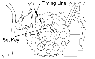
    3. Install the crankshaft pulley set bolt, and turn the crankshaft to align the crankshaft set key with the timing line of the cylinder block.


    A076297E04
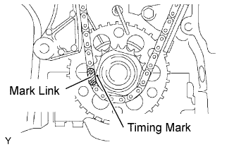
  1. Align the mark link (yellow) with the timing mark of the crankshaft timing gear.


    G038092E03
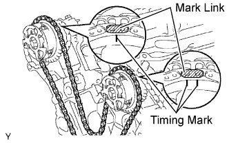
  1. Align the mark links (orange) with the timing marks of the camshaft timing gears, and install the No. 1 chain.


7. INSTALL NO. 2 CHAIN VIBRATION DAMPER


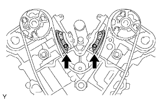
    G036844E01
  1. Install the 2 No. 2 chain vibration dampers.


8. INSTALL NO. 1 IDLE GEAR SHAFT
  1. Apply a light coat of engine oil to the rotating surface of the No. 1 idle gear shaft.


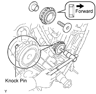
    A076299E03
  1. Temporarily install the No. 1 idle gear shaft and No. 1 idle gear with the No. 2 idle gear shaft while aligning the knock pin of the No. 1 idle gear shaft with the knock pin groove of the cylinder block.

    NOTICE:
    Be careful of the idle gear direction.

  1. Using a 10 mm hexagon wrench, tighten the No. 2 idle gear shaft.

    Torque:
    60 N*m{ 612 kgf*cm , 44 ft.*lbf }

  1. Remove the bar from the chain tensioner.


9. INSTALL TIMING CHAIN COVER SUB-ASSEMBLY
  1. Install the timing chain cover (Click here).