 |
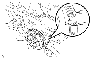
Turn the crankshaft pulley, and align its groove with the timing mark "0" of the timing chain cover.
CAMSHAFT (for Bank 2) > REMOVAL |
| 1. REMOVE TIMING CHAIN COVER SUB-ASSEMBLY |
Remove the timing chain cover (Click here).
| 2. SET NO. 1 CYLINDER TO TDC / COMPRESSION |
|
Turn the crankshaft pulley, and align its groove with the timing mark "0" of the timing chain cover.
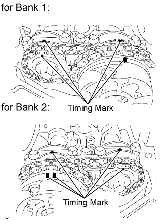 |
Check that the timing marks of the camshaft timing gears and sprockets are aligned with the timing marks of the bearing caps shown in the illustration.
If not, turn the crankshaft 1 complete revolution (360°) and align the timing marks as above.
| 3. REMOVE NO. 1 CHAIN TENSIONER ASSEMBLY |
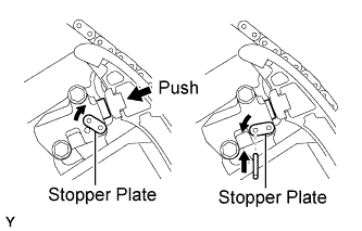 |
While turning the stopper plate of the tensioner clockwise, push in the plunger of the chain tensioner as shown in the illustration.
While turning the stopper plate of the tensioner counterclockwise, insert a bar of φ 3.5 mm (0.138 in.) into the holes on the stopper plate and tensioner to fix the stopper plate.
Remove the 2 bolts and chain tensioner.
| 4. REMOVE CHAIN TENSIONER SLIPPER |
Remove the chain tensioner slipper.
| 5. REMOVE NO. 1 IDLE GEAR SHAFT |
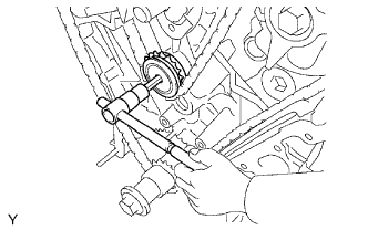 |
Using a 10 mm hexagon wrench, remove the No. 2 idle gear shaft, No. 1 idle gear and No. 1 idle gear shaft.
| 6. REMOVE NO. 2 CHAIN VIBRATION DAMPER |
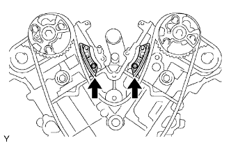 |
Remove the 2 No. 2 chain vibration dampers.
| 7. REMOVE NO. 1 CHAIN |
Remove the No. 1 chain.
| 8. REMOVE NO. 1 CHAIN VIBRATION DAMPER |
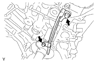 |
Remove the 2 bolts and No. 1 chain vibration damper.
| 9. REMOVE CAMSHAFT TIMING GEARS AND NO. 2 CHAIN |
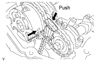 |
While raising the No. 3 chain tensioner, insert a pin of φ 1.0 mm (0.0394 in.) into the hole to fix it.
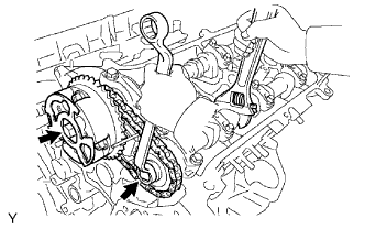 |
Hold the hexagonal portion of the camshaft with a wrench, and remove the 2 bolts, camshaft timing gear, camshaft timing sprocket and No. 2 chain.
| 10. REMOVE NO. 3 CHAIN TENSIONER ASSEMBLY |
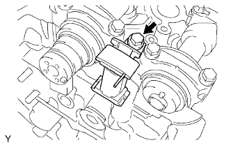 |
Remove the bolt and No. 3 chain tensioner.
| 11. REMOVE NO. 3 CAMSHAFT AND NO. 4 CAMSHAFT |
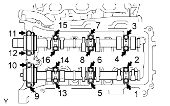 |
Uniformly loosen and remove the 16 bearing cap bolts in the sequence shown in the illustration.
Remove the 8 bearing caps and 2 camshafts.