 |
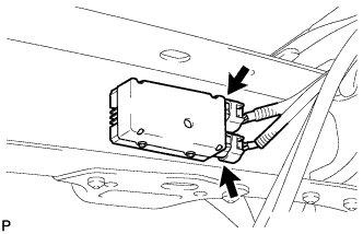
Disconnect the 2 fuel pump ECU connectors.
INTAKE MANIFOLD > REMOVAL |
| 1. DISCHARGE FUEL SYSTEM PRESSURE |
Disconnect the cable from the negative (-) battery terminal.
|
Disconnect the 2 fuel pump ECU connectors.
Connect the cable to the negative (-) battery terminal.
Start the engine. After the engine has stopped on its own, turn the ignition switch OFF.
Crank the engine again, then check that the engine does not start.
Loosen the fuel tank cap, then discharge the pressure in the fuel tank completely.
Connect the 2 fuel pump ECU connectors.
| 2. DISCONNECT CABLE FROM NEGATIVE BATTERY TERMINAL |
| 3. REMOVE NO. 1 ENGINE UNDER COVER |
Remove the 5 bolts, 3 screws and engine under cover.
| 4. DRAIN ENGINE COOLANT |
Loosen the radiator drain cock plug and 2 cylinder block drain cock plugs.
Remove the radiator cap. Then drain the coolant.
Tighten the 2 cylinder block drain cock plugs.
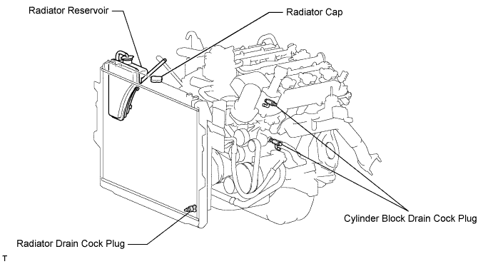
Tighten the radiator drain cock plug by hand.
| 5. REMOVE FRONT WIPER MOTOR AND LINK ASSEMBLY |
Remove the front wiper motor and link (Click here).
| 6. REMOVE FRONT COWL TOP OUTER PANEL SUB-ASSEMBLY |
Disconnect the 2 washer hoses.
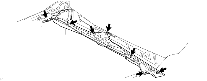
Remove the 7 bolts and front cowl top outer panel.
| 7. REMOVE V-BANK COVER |
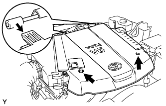 |
Remove the 2 nuts and V-bank cover.
| 8. REMOVE NO. 2 AIR CLEANER HOSE |
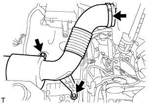 |
Loosen the hose clamp.
Remove the 2 bolts and air cleaner hose.
| 9. REMOVE AIR CLEANER ASSEMBLY WITH ELEMENT |
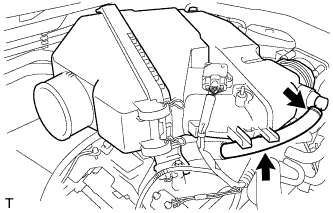 |
Disconnect the No. 2 ventilation hose.
Detach the hose clamp.
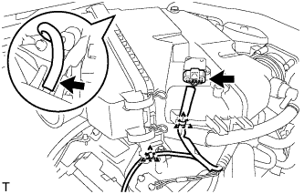 |
Disconnect the vacuum hose.
Disconnect the MAF meter connector.
Using a clip remover, detach the 2 wire harness clamps.
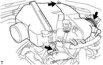 |
Loosen the hose clamp.
Remove the 2 bolts and air cleaner with element.
| 10. REMOVE INTAKE AIR SURGE TANK |
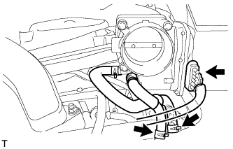 |
Disconnect the throttle position sensor and throttle control motor connector.
Disconnect the No. 4 water by-pass hose.
Disconnect the No. 5 water by-pass hose.
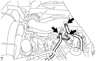 |
Disconnect the purge line hose.
Disconnect the purge VSV connector.
Disconnect the union to check valve hose.
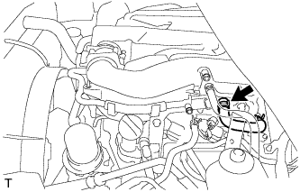 |
Disconnect the No. 1 ventilation hose.
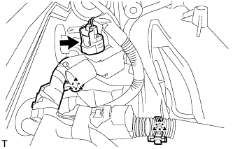 |
Disconnect the vacuum switching valve (for ACIS) connector.
Using a clip remover, detach the 2 wire harness clamps.
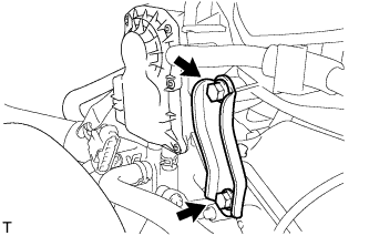 |
Remove the 2 bolts and throttle body bracket.
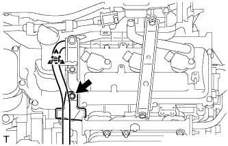 |
Using a clip remover, detach the wire harness clamp.
Remove the bolt and oil baffle plate.
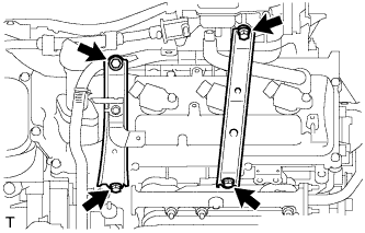 |
Remove the 2 bolts and No. 1 surge tank stay.
Remove the 2 bolts and No. 2 surge tank stay.
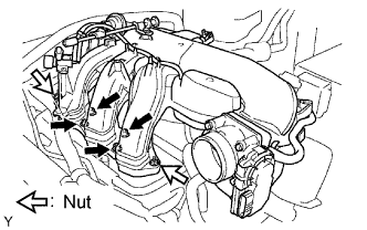 |
Remove the 2 nuts.
Using an 8 mm hexagon wrench, remove the 4 bolts. Then remove the intake air surge tank and gasket.
| 11. REMOVE FUEL DELIVERY PIPE SUB-ASSEMBLY |
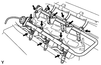 |
Disconnect the 6 fuel injector connectors.
Remove the 6 bolts and fuel delivery pipe together with the 6 fuel injectors.
| 12. REMOVE INTAKE MANIFOLD SUB-ASSEMBLY |
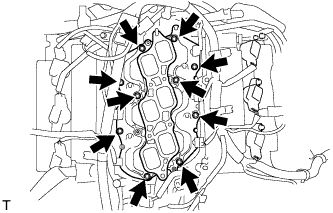 |
Remove the 10 bolts, intake manifold and 2 gaskets.