 |
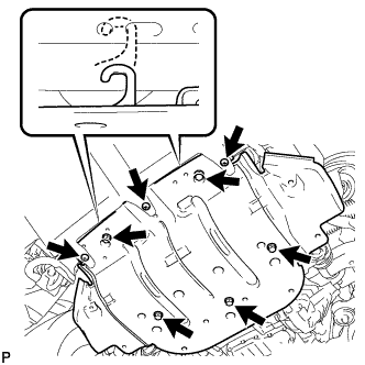
Remove the 3 screws and 5 bolts.
STARTER > REMOVAL |
| 1. DISCONNECT CABLE FROM NEGATIVE BATTERY TERMINAL |
| 2. REMOVE NO. 1 ENGINE UNDER COVER |
|
Remove the 3 screws and 5 bolts.
Unhook the engine under cover from the vehicle body as shown in the illustration.
| 3. REMOVE V-BANK COVER SUB-ASSEMBLY |
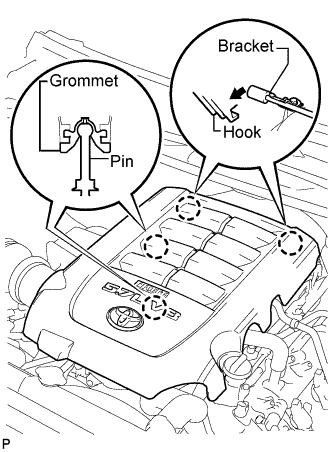 |
Raise the front of the V-bank cover to detach the 2 pins. Then remove the 2 V-bank cover hooks from the bracket, and remove the V-bank cover.
| 4. REMOVE AIR CLEANER HOSE ASSEMBLY |
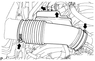 |
Disconnect the vacuum hose and ventilation hose.
Loosen the 2 clamps.
Remove the air cleaner hose.
| 5. REMOVE AIR CLEANER ASSEMBLY |
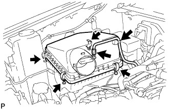 |
Remove the air cleaner cap.
Disconnect the MAF meter connector.
Using a clip remover, detach the wire harness clamp.
Unfasten the 4 hook clamps and then remove the air cleaner cap.
Remove the air cleaner element.
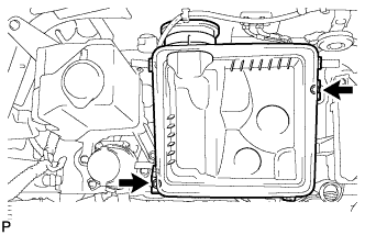 |
Remove the 2 bolts and air cleaner case.
| 6. REMOVE FAN AND GENERATOR V BELT |
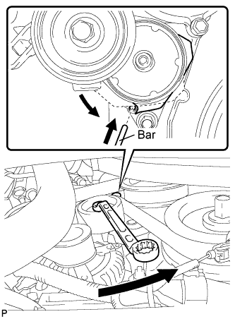 |
While turning the belt tensioner counterclockwise, align the service hole for the belt tensioner and the belt tensioner fixing position, and then insert a bar of φ 5 mm (0.197 in.) into the service hole to fix the belt tensioner in place.
Remove the V belt.
| 7. REMOVE FRONT FENDER APRON SEAL RH |
Remove the 5 clips and apron seal.
| 8. DISCONNECT VANE PUMP ASSEMBLY |
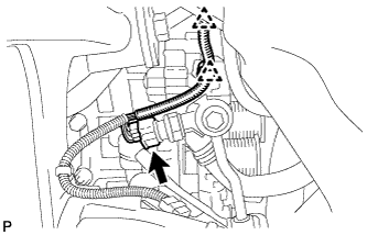 |
Disconnect the 2 clamps and power steering oil pressure switch connector.
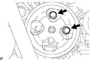 |
Remove the 2 bolts and disconnect the vane pump.
| 9. REMOVE GENERATOR ASSEMBLY |
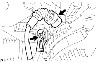 |
Disconnect the generator connector.
Remove the terminal cap and nut, and disconnect the generator wire.
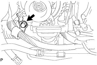 |
Remove the bolt and disconnect the wire harness bracket from the generator.
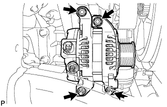 |
Remove the 2 bolts, 2 nuts and generator.
| 10. REMOVE ENGINE OIL LEVEL DIPSTICK GUIDE |
Remove the dipstick.
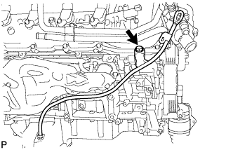 |
Remove the bolt and dipstick guide.
Remove the O-ring from the dipstick guide.
| 11. REMOVE FRONT EXHAUST PIPE ASSEMBLY |
Disconnect the air fuel ratio sensor connector.
Disconnect the heated oxygen sensor connector and 2 clamps.
Remove the 2 bolts.
Remove the 3 nuts and front exhaust pipe.
Remove the 2 gaskets.
| 12. REMOVE NO. 1 EXHAUST MANIFOLD HEAT INSULATOR |
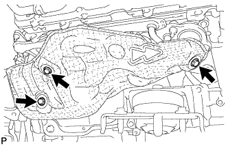 |
Remove the 3 bolts and heat insulator.
| 13. REMOVE EXHAUST MANIFOLD SUB-ASSEMBLY RH |
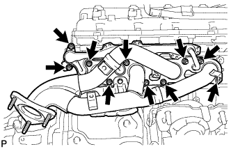 |
Remove the 10 nuts, exhaust manifold and 2 gaskets.
| 14. REMOVE STARTER COVER |
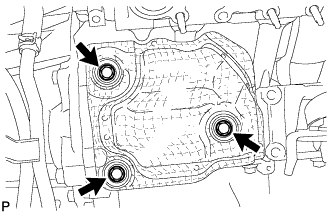 |
Remove the 3 bolts and starter cover.
| 15. REMOVE STARTER ASSEMBLY |
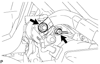 |
Disconnect the starter connector.
Remove the nut and disconnect the starter wire.
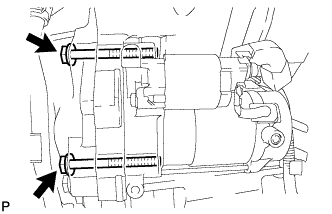 |
Remove the 2 bolts and starter.
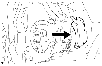 |
Remove the flywheel housing side cover.