 |
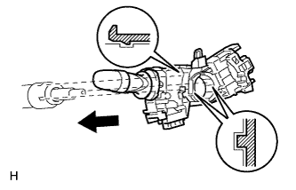
Insert the headlight dimmer switch assembly onto the steering column while making sure that the switch's protrusions align with the shaft's cutout parts.
HEADLIGHT DIMMER SWITCH > INSTALLATION |
| 1. INSTALL HEADLIGHT DIMMER SWITCH ASSEMBLY |
|
Insert the headlight dimmer switch assembly onto the steering column while making sure that the switch's protrusions align with the shaft's cutout parts.
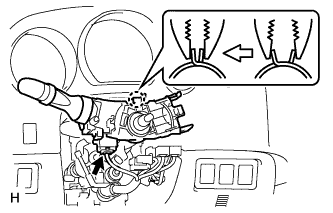 |
While loosening the band clamp, attach the claw to install the headlight dimmer switch assembly.
Connect the connector.
| 2. INSTALL WINDSHIELD WIPER SWITCH ASSEMBLY |
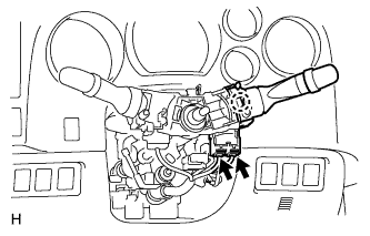 |
Attach the claw to install the windshield wiper switch.
Connect the connectors.
| 3. INSTALL SPIRAL CABLE SUB-ASSEMBLY |
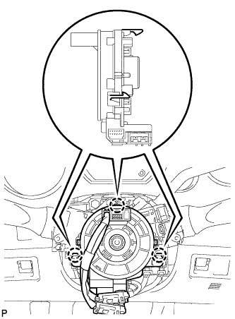 |
Attach the 3 claws and install the spiral cable with steering sensor.
Connect the connectors to the spiral cable with steering sensor.
| 4. INSTALL TILT AND TELESCOPIC MANUAL SWITCH (for Power Tilt and Power Telescopic Steering Column) |
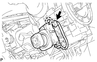 |
Attach the claw to install the tilt and telescopic switch.
Connect the connector.
| 5. INSTALL UPPER STEERING COLUMN COVER (for Manual Tilt) |
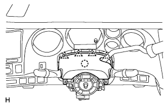 |
Attach the claw to install the upper steering column cover.
Attach the 4 clips.
| 6. INSTALL UPPER STEERING COLUMN COVER (for Manual Tilt and Manual Telescopic Steering Column) |
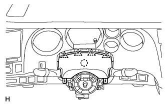 |
Attach the claw to install the upper steering column cover.
Attach the 4 clips.
| 7. INSTALL UPPER STEERING COLUMN COVER (for Power Tilt and Power Telescopic Steering Column) |
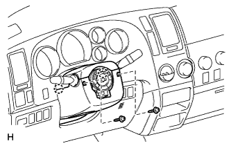 |
Attach the 2 claws to install the column cover.
Install the 2 screws.
| 8. INSTALL LOWER STEERING COLUMN COVER (for Manual Tilt) |
|
Attach the 2 claws to install the lower steering column cover.
Install the 2 screws.
| 9. INSTALL LOWER STEERING COLUMN COVER (for Manual Tilt and Manual Telescopic Steering Column) |
|
Attach the 2 claws to install the lower steering column cover.
Install the 2 screws.
| 10. INSTALL LOWER STEERING COLUMN COVER (for Power Tilt and Power Telescopic Steering Column) |
|
Attach the claw to install the upper steering column cover.
Attach the 4 clips.
| 11. INSTALL STEERING WHEEL ASSEMBLY |
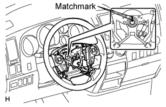 |
Align the matchmarks on the steering wheel and steering main shaft.
Install the steering wheel set nut.
| 12. INSTALL STEERING PAD (w/ Steering Pad Switch) |
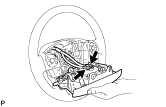 |
Support the steering pad with one hand.
Connect the 2 connectors to the steering pad.
Confirm that the circumference groove of the screw fits in the screw case, and place the steering pad onto the steering wheel .
Using a T30 "TORX" socket wrench, tighten the 2 screws.
| 13. INSTALL STEERING PAD (w/o Steering Pad Switch) |
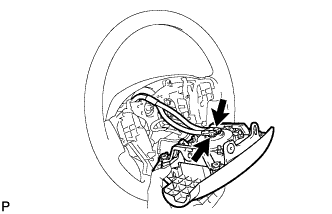 |
Support the steering pad with one hand.
Connect the 2 connectors to the steering pad.
Confirm that the circumference groove of the screw fits in the screw case, and place the steering pad onto the steering wheel.
Using a T30 "TORX" socket wrench, tighten the 2 screws.
| 14. INSTALL LOWER NO. 3 STEERING WHEEL COVER |
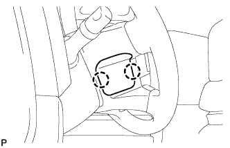 |
Attach the 2 claws to install the cover.
| 15. INSTALL LOWER NO. 2 STEERING WHEEL COVER |
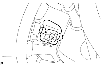 |
w/ Cruise Control:
Attach the 2 claws to install the cover.
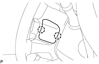 |
w/o Cruise Control:
Attach the 2 claws to install the cover.
| 16. CONNECT CABLE TO NEGATIVE BATTERY TERMINAL |
| 17. CHECK SRS WARNING LIGHT |
Check the SRS warning light (Click here).