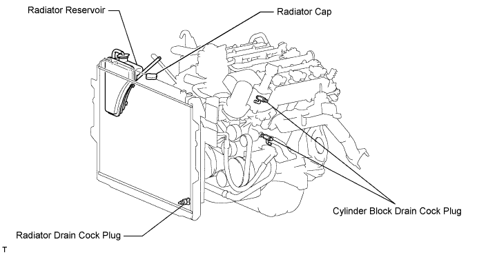
Tighten the 2 cylinder block drain cock plugs.
- Torque:
- 13 N*m{ 133 kgf*cm , 10 ft.*lbf }
AIR SWITCHING VALVE > REMOVAL |
| 1. DISCONNECT CABLE FROM NEGATIVE BATTERY TERMINAL |
| 2. REMOVE NO. 1 ENGINE UNDER COVER |
Remove the 5 bolts, 3 screws and engine under cover.
| 3. DRAIN ENGINE COOLANT |
Loosen the radiator drain cock plug and 2 cylinder block drain cock plugs.
Remove the radiator cap. Then drain the coolant.
Tighten the 2 cylinder block drain cock plugs.
Tighten the radiator drain cock plug by hand.
| 4. REMOVE FRONT WIPER MOTOR AND LINK ASSEMBLY |
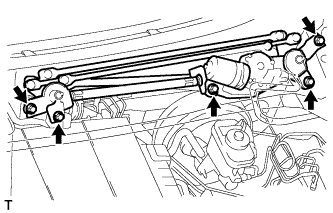 |
Disconnect the connector.
Remove the nut.
Remove the 4 bolts and wiper motor and link assembly.
| 5. REMOVE FRONT COWL TOP OUTER PANEL SUB-ASSEMBLY |
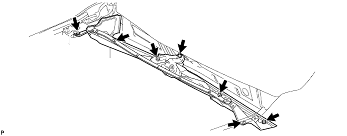
Disconnect the 2 washer hoses.
Remove the 7 bolts and front cowl top outer panel.
| 6. REMOVE V-BANK COVER |
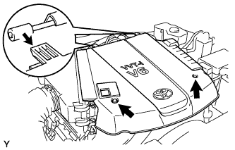 |
Remove the 2 nuts and V-bank cover.
| 7. REMOVE NO. 2 AIR CLEANER HOSE |
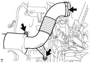 |
Loosen the hose clamp.
Remove the 2 bolts and air cleaner hose.
| 8. REMOVE AIR CLEANER ASSEMBLY WITH ELEMENT |
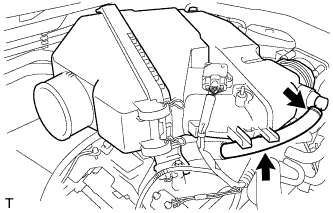 |
Disconnect the No. 2 ventilation hose.
Detach the hose clamp.
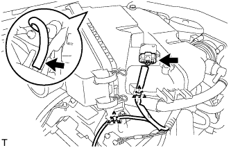 |
Disconnect the vacuum hose.
Disconnect the MAF meter connector.
Using a clip remover, detach the 2 wire harness clamps.
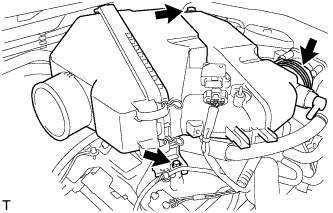 |
Loosen the hose clamp.
Remove the 2 bolts and air cleaner with element.
| 9. REMOVE INTAKE AIR SURGE TANK |
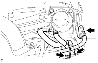 |
Disconnect the throttle position sensor and throttle control motor connector.
Disconnect the No. 4 water by-pass hose.
Disconnect the No. 5 water by-pass hose.
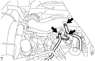 |
Disconnect the purge line hose.
Disconnect the purge VSV connector.
Disconnect the union to check valve hose.
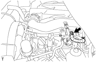 |
Disconnect the No. 1 ventilation hose.
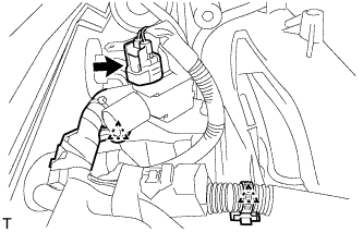 |
Disconnect the vacuum switching valve (for ACIS) connector.
Using a clip remover, detach the 2 wire harness clamps.
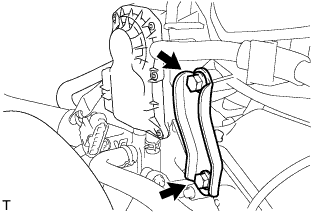 |
Remove the 2 bolts and throttle body bracket.
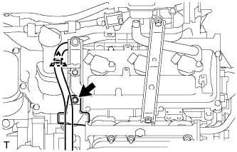 |
Using a clip remover, detach the wire harness clamp.
Remove the bolt and oil baffle plate.
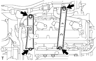 |
Remove the 2 bolts and No. 1 surge tank stay.
Remove the 2 bolts and No. 2 surge tank stay.
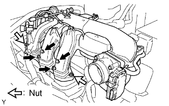 |
Remove the 2 nuts.
Using an 8 mm hexagon wrench, remove the 4 bolts. Then remove the intake air surge tank and gasket.
| 10. DISCONNECT NO. 3 AIR INJECTION SYSTEM HOSE |
Disconnect the air injection system hose from the air tube.
| 11. DISCONNECT NO. 2 AIR INJECTION SYSTEM HOSE |
Disconnect the air injection system hose from the air tube.
| 12. REMOVE NO. 5 AIR INJECTION SYSTEM HOSE |
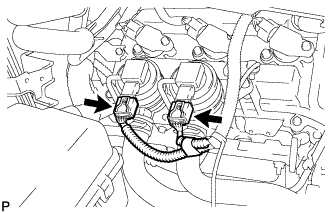 |
Disconnect the 2 air pump connectors.
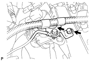 |
Detach the wire harness clamp and remove the bolt, then disconnect the wire harness bracket.
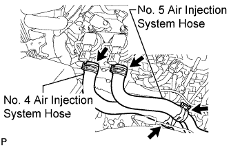 |
Remove the air injection system hose.
| 13. REMOVE NO. 4 AIR INJECTION SYSTEM HOSE |
| 14. REMOVE AIR TUBE |
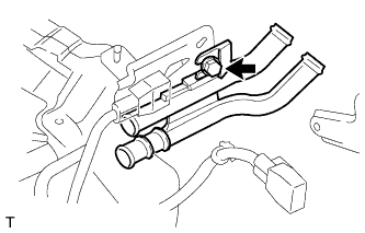 |
Remove the bolt and air tube.
| 15. REMOVE NO. 1 AIR TUBE |
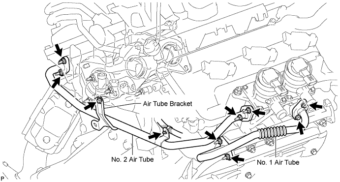
Remove the 2 bolts, 2 nuts, No. 1 air tube and 2 gaskets.
| 16. DISCONNECT NO. 2 AIR TUBE |
Disconnect the wire harness clamp.
Remove the bolts and 4 nuts, then disconnect the No. 2 air tube.
Remove the 2 gaskets.
| 17. REMOVE AIR SWITCHING VALVE ASSEMBLY |
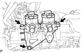 |
Remove the 2 nuts, bolt and air switching valve.