AIR SWITCHING VALVE (for Bank 2) > INSTALLATION |
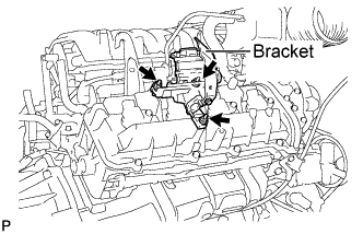
| 1. INSTALL AIR SWITCHING VALVE ASSEMBLY |
|
Install the air switching valve with the 3 nuts.
| 2. INSTALL NO. 2 AIR TUBE |
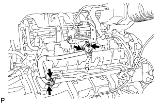 |
Temporarily install a new gasket and the No. 2 air tube to the exhaust manifold side with the 2 nuts.
Install a new gasket and the No. 2 air tube to the air switching valve side with the 2 nuts.
Tighten the 2 nuts on the exhaust manifold side.
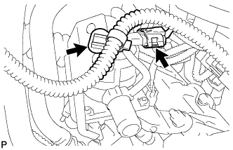 |
Connect the air pump connector.
Connect the wire harness clamp.
| 3. INSTALL NO. 2 AIR INJECTION SYSTEM HOSE |
Connect the air injection system hose to the air switching valve.
| 4. CONNECT NO. 1 WATER BY-PASS PIPE |
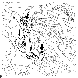 |
Connect the water by-pass pipe with the 2 bolts.
| 5. INSTALL FRONT FENDER APRON SEAL RH |
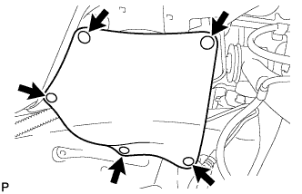 |
Install the fender apron seal with the 5 clips.
| 6. CONNECT CABLE TO NEGATIVE BATTERY TERMINAL |