 |
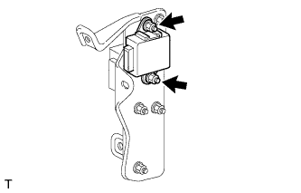
Install the clearance warning ECU to the bracket with the 2 nuts.
- NOTICE:
- Avoid any impact to the clearance warning ECU.
- Do not drop the ECU. If it is dropped, replace it with a new one.
CLEARANCE WARNING ECU > INSTALLATION |
| 1. INSTALL CLEARANCE WARNING ECU |
|
Install the clearance warning ECU to the bracket with the 2 nuts.
| 2. INSTALL CLEARANCE WARNING ECU WITH BRACKET |
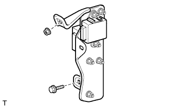 |
Install the ECU with bracket with the nut and bolt.
Connect the ECU connectors.
| 3. INSTALL LOWER INSTRUMENT PANEL FINISH PANEL SUB-ASSEMBLY RH |
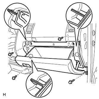 |
Attach the 3 claws to install the finish panel.
Install the 3 screws.
Install the bolt.
| 4. INSTALL INSTRUMENT SIDE PANEL RH |
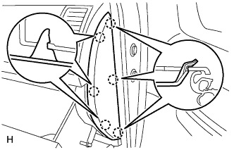 |
Attach the 6 claws to install the side panel.
| 5. CONNECT CABLE TO NEGATIVE BATTERY TERMINAL |