 |
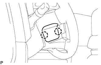
Using a screwdriver, remove the steering wheel cover.
- HINT:
- Tape the screwdriver tip before use.
STEERING COLUMN ASSEMBLY (for Power Tilt and Power Telescopic Steering Column) > REMOVAL |
| 1. PLACE FRONT WHEELS FACING STRAIGHT AHEAD |
| 2. DISCONNECT CABLE FROM NEGATIVE BATTERY TERMINAL |
| 3. REMOVE LOWER NO. 3 STEERING WHEEL COVER |
|
Using a screwdriver, remove the steering wheel cover.
| 4. REMOVE LOWER NO. 2 STEERING WHEEL COVER |
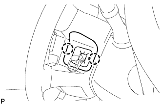 |
w/ Cruise Control:
Using a screwdriver, remove the No. 2 steering wheel cover.
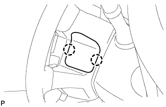 |
w/o Cruise Control:
Using a screwdriver, remove the No. 2 steering wheel cover.
| 5. REMOVE STEERING PAD (w/ Steering Pad Switch) |
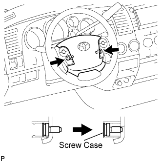 |
Using a T30 "TORX" socket wrench, loosen the 2 screws until the groove along the screw circumference catches on the screw case.
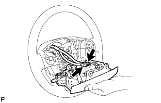 |
Pull out the steering pad from the steering wheel, as shown in the illustration. Then support the steering pad with one hand.
Disconnect the 2 connectors and remove the steering pad.
| 6. REMOVE STEERING PAD (w/o Steering Pad Switch) |
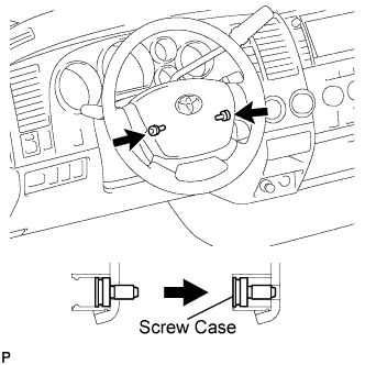 |
Using a T30 "TORX" socket wrench, loosen the 2 screws until the groove along the screw circumference catches on the screw case.
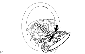 |
Pull out the steering pad from the steering wheel, as shown in the illustration. Then support the steering pad with one hand.
Disconnect the 2 connectors and remove the steering pad.
| 7. REMOVE STEERING WHEEL ASSEMBLY |
Remove the steering wheel set nut.
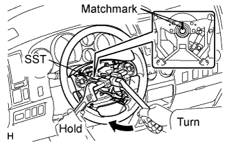 |
Put matchmarks on the steering wheel and main shaft.
Using SST, remove the steering wheel.
| 8. REMOVE LOWER STEERING COLUMN COVER |
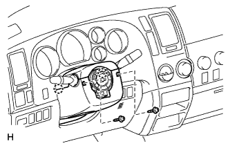 |
Remove the 2 screws.
Detach the 2 claws to remove the lower steering column cover.
| 9. REMOVE UPPER STEERING COLUMN COVER |
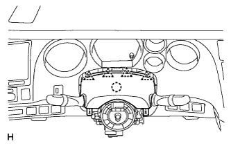 |
Detach the 4 clips.
Detach the claw to remove the upper steering column cover.
| 10. REMOVE TILT AND TELESCOPIC MANUAL SWITCH |
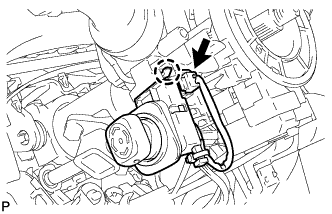 |
Disconnect the connector.
Using a screwdriver, detach the claw and pull out the tilt and telescopic switch.
| 11. REMOVE TURN SIGNAL SWITCH ASSEMBLY WITH SPIRAL CABLE SUB-ASSEMBLY |
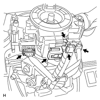 |
Disconnect the 5 connectors from the turn signal switch with spiral cable.
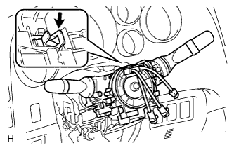 |
Using pliers, grip the claws of the clamp and remove the turn signal switch with spiral cable from the steering column.
| 12. REMOVE FRONT DOOR SCUFF PLATE LH (for Regular Cab) |
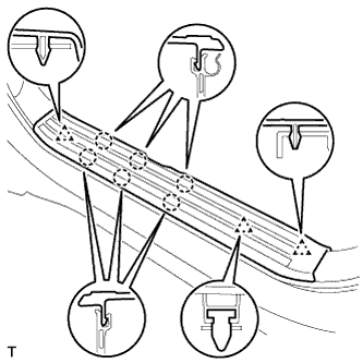 |
Detach the 6 claws and 3 clips, and remove the scuff plate.
| 13. REMOVE FRONT DOOR SCUFF PLATE LH (for Double Cab, CrewMax) |
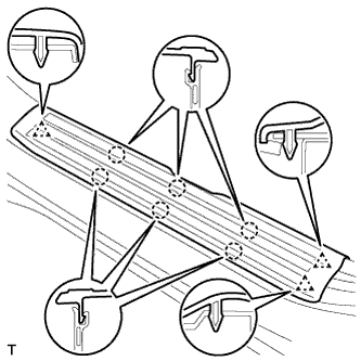 |
Detach the 6 claws and 3 clips, and remove the scuff plate.
| 14. REMOVE COWL SIDE TRIM BOARD LH |
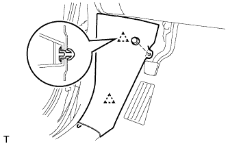 |
Remove the clip.
Detach the 2 clips and remove the cowl side trim board.
| 15. REMOVE INSTRUMENT SIDE PANEL LH |
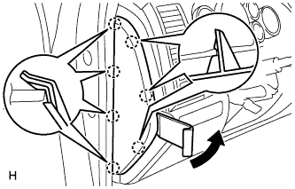 |
Using a moulding remover, detach the 7 claws and remove the side panel.
| 16. REMOVE LOWER INSTRUMENT PANEL FINISH PANEL SUB-ASSEMBLY LH |
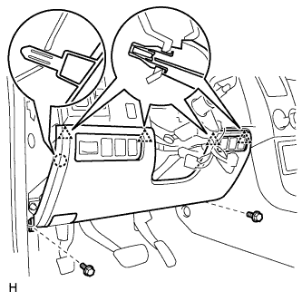 |
Remove the hood lock control lever.
Remove the 2 bolts.
Detach the 4 clips and claw.
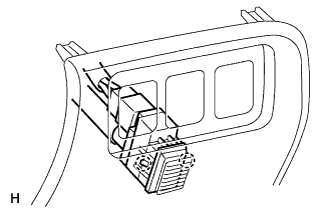 |
for Automatic Air Conditioning System:
Detach the 2 claws and remove the sensor.
Remove the finish panel and then disconnect the connectors.
| 17. REMOVE NO. 1 INSTRUMENT PANEL SAFETY PAD INSERT |
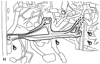 |
Remove the 4 bolts.
Detach the 2 claws.
Remove the safety pad and then disconnect the connector.
| 18. REMOVE NO. 1 AIR DUCT SUB-ASSEMBLY |
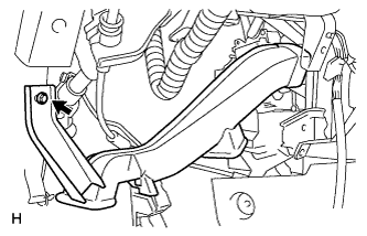 |
Remove the bolt and air duct.
| 19. REMOVE STEERING INTERMEDIATE SHAFT ASSEMBLY |
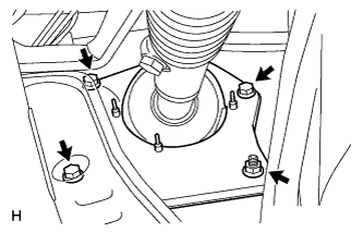 |
Remove the 3 bolts and nut.
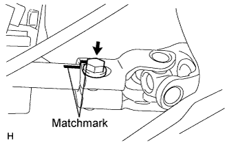 |
Put matchmarks on the steering intermediate shaft and the steering column.
Remove the bolt and steering intermediate shaft from the steering column.
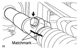 |
Put matchmarks on the No. 2 steering intermediate shaft and steering intermediate shaft.
Remove the bolt and steering intermediate shaft from the No. 2 steering intermediate shaft.
| 20. REMOVE NO. 2 STEERING INTERMEDIATE SHAFT SUB-ASSEMBLY |
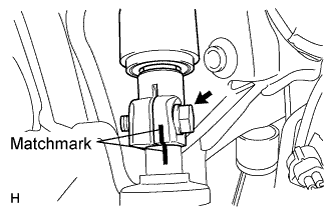 |
Put matchmarks on the No. 2 steering intermediate shaft and power steering gear.
Remove the bolt and No. 2 steering intermediate shaft from the power steering gear.
| 21. REMOVE STEERING COLUMN ASSEMBLY |
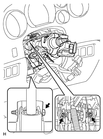 |
Remove the bolt and 2 nuts. Then remove the steering column from the instrument panel reinforcement.