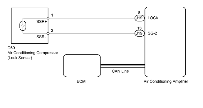
DTC B1422/22 Compressor Lock Sensor Circuit |
| DTC Code | DTC Detection Condition | Trouble Area |
| B1422/22 | Open or short in compressor lock sensor circuit |
|
| 1.CHECK FOR DTC (CAN COMMUNICATION SYSTEM) |
Use the Techstream to check if the CAN communication system is functioning normally.
| Result | Proceed to |
| CAN DTC is not output | A |
| CAN DTC is output | B |
|
| ||||
| A | |
 |
| 2.CHECK AIR CONDITIONING AMPLIFIER |
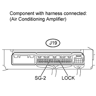  |
Remove the air conditioning amplifier with the connectors still connected (Click here).
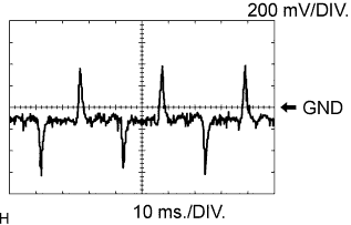
Using an oscilloscope, check the waveform.
| Tester Connection | Tool Setting | Condition | Specified Condition |
| J19-8 (LOCK) - J19-13 (SG-2) | 200 mV/DIV., 10 ms./DIV. | Engine is running A/C switch ON Blower switch LO | Pulse generation |
| Result | Proceed to |
| NG | A |
| OK (Checking from the PROBLEM SYMPTOMS TABLE) | B |
| OK (Checking from the DTC) | C |
|
| ||||
|
| ||||
| A | |
|
| 3.INSPECT AIR CONDITIONING COMPRESSOR (LOCK SENSOR) |
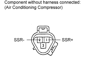 |
Disconnect the connector from the air conditioning compressor.
Measure the resistance according to the value(s) in the table below.
| Tester Connection | Condition | Specified Condition |
| 1 (SSR+) - 2 (SSR-) | 20°C (68°F) | 65 to 125 Ω |
| Result | Proceed to |
| OK | A |
| NG (for 2UZ-FE) | B |
| NG (for 3UR-FE or 3UR-FBE) | C |
|
| ||||
|
| ||||
| A | |
|
| 4.CHECK HARNESS AND CONNECTOR (AIR CONDITIONING AMPLIFIER - AIR CONDITIONING COMPRESSOR) |
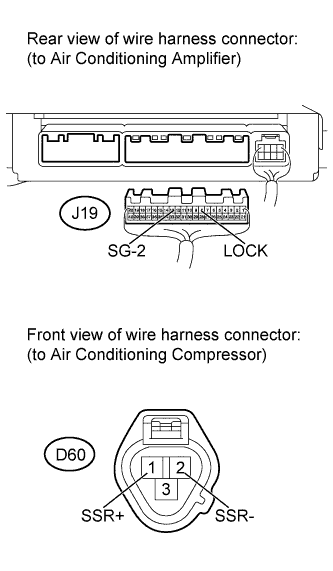 |
Disconnect the J19 air conditioning amplifier connector.
Disconnect the D60 air conditioning compressor connector.
Measure the resistance according to the value(s) in the table below.
| Tester Connection | Condition | Specified Condition |
| J19-8 (LOCK) - D60-1 (SSR+) | Always | Below 1 Ω |
| J19-13 (SG-2) - D60-2 (SSR-) | ||
| J19-8 (LOCK) or D60-1 (SSR+) - Body ground | Always | 10 kΩ or higher |
| J19-13 (SG-2) or D60-2 (SSR-) - Body ground |
|
| ||||
| OK | ||
 | ||
| ||
