 |
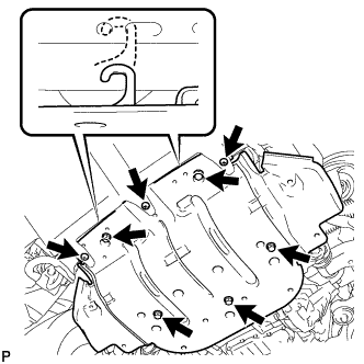
Remove the 3 screws and 5 bolts.
EXHAUST MANIFOLD > REMOVAL |
| 1. DISCONNECT CABLE FROM NEGATIVE BATTERY TERMINAL |
| 2. REMOVE NO. 1 ENGINE UNDER COVER |
|
Remove the 3 screws and 5 bolts.
Unhook the engine under cover from the vehicle body as shown in the illustration.
| 3. DRAIN ENGINE COOLANT |
Loosen the radiator drain cock plug.
Remove the radiator cap. Then drain the coolant from the radiator.
Loosen the 2 cylinder block drain cock plugs. Then drain the coolant from the engine.
Tighten the 2 cylinder block drain cock plugs.
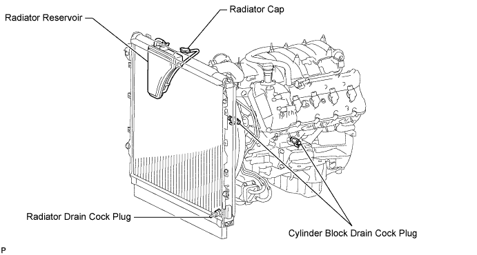
Tighten the radiator drain cock plug by hand.
| 4. REMOVE V-BANK COVER SUB-ASSEMBLY |
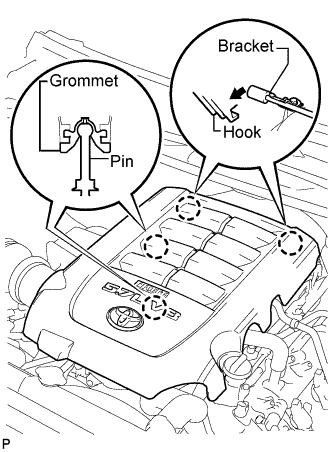 |
Raise the front of the V-bank cover to detach the 2 pins. Then remove the 2 V-bank cover hooks from the bracket, and remove the V-bank cover.
| 5. REMOVE AIR CLEANER HOSE ASSEMBLY |
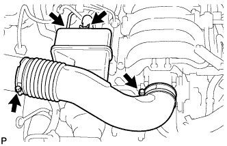 |
Disconnect the vacuum hose and No. 2 ventilation hose.
Loosen the 2 hose clamps.
Remove the air cleaner hose.
| 6. REMOVE AIR CLEANER ASSEMBLY |
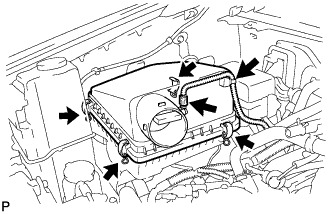 |
Remove the air cleaner cap.
Disconnect the MAF meter connector.
Using a clip remover, detach the wire harness clamp.
Unfasten the 4 hook clamps and then remove the air cleaner cap.
Remove the air cleaner element.
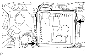 |
Remove the 2 bolts and air cleaner case.
| 7. DISCONNECT INLET RADIATOR HOSE |
| 8. DISCONNECT OUTLET RADIATOR HOSE |
| 9. REMOVE FAN AND GENERATOR V-BELT |
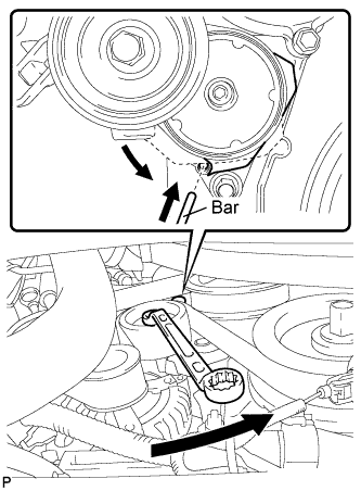 |
While turning the belt tensioner counterclockwise, align the service hole for the belt tensioner and the belt tensioner fixing position, and then insert a bar of φ 5 mm (0.197 in.) into the service hole to fix the belt tensioner in place.
Remove the V belt.
| 10. REMOVE FAN SHROUD |
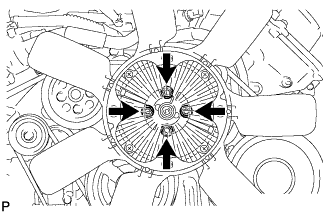 |
Loosen the 4 nuts holding the fluid coupling fan.
Remove the fan and generator V-belt.
Disconnect the reservoir hose from the upper radiator tank.
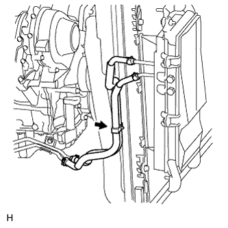 |
w/ Trailer Towing System:
Detach the claw to open the No. 1 flexible hose clamp.
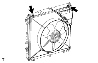 |
Remove the 2 bolts holding the fan shroud.
Remove the 4 nuts of the fluid coupling fan, and then remove the shroud together with the coupling fan.
Remove the fan pulley from the fan bracket.
| 11. REMOVE FRONT FENDER APRON SEAL RH |
Remove the 6 clips and fender apron seal.
| 12. REMOVE FRONT FENDER APRON SEAL REAR RH |
Remove the 5 clips and fender apron seal.
| 13. REMOVE FRONT FENDER APRON SEAL LH |
Remove the 6 clips and fender apron seal.
| 14. REMOVE FRONT FENDER APRON SEAL REAR LH |
Remove the 5 clips and fender apron seal.
| 15. REMOVE ENGINE OIL LEVEL DIPSTICK GUIDE |
Remove the dipstick.
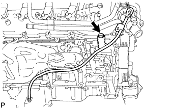 |
Remove the bolt and dipstick guide.
Remove the O-ring from the dipstick guide.
| 16. DISCONNECT VANE PUMP ASSEMBLY |
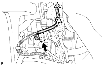 |
Disconnect the 2 clamps and power steering oil pressure switch connector.
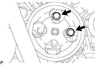 |
Remove the 2 bolts and disconnect the vane pump.
| 17. REMOVE GENERATOR ASSEMBLY |
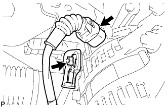 |
Disconnect the generator connector.
Remove the terminal cap and nut, and disconnect the generator wire.
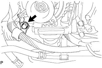 |
Remove the bolt and disconnect the wire harness bracket from the generator.
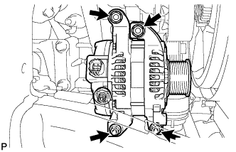 |
Remove the 2 bolts, 2 nuts and generator.
| 18. DISCONNECT COOLER COMPRESSOR ASSEMBLY |
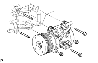 |
Remove the 2 bolts, 2 nuts and 2 stud bolts, and disconnect the cooler compressor.
| 19. REMOVE PROPELLER SHAFT HEAT INSULATOR (for 4WD) |
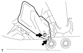 |
Remove the 2 bolts and heat insulator.
| 20. REMOVE FRONT PROPELLER SHAFT ASSEMBLY (for 4WD) |
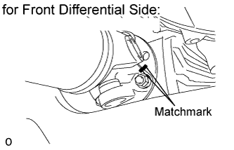 |
for Front Differential Side:
Place matchmarks on the differential and propeller shaft flange.
Remove the 4 nuts, 4 washers and disconnect the propeller shaft from the differential.
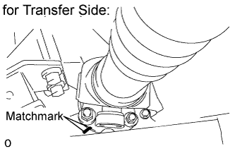 |
for Transfer Side:
Place matchmarks on the transfer and propeller shaft flanges.
Remove the 4 nuts and 4 washers.
Remove the propeller shaft from the transfer flange.
| 21. REMOVE FRONT NO. 2 EXHAUST PIPE ASSEMBLY (for Regular Cab Standard Deck) |
Disconnect the air fuel ratio sensor connector.
Disconnect the heated oxygen sensor connector.
Remove the 2 bolts, 5 nuts, No. 2 exhaust pipe and 2 gaskets.
| 22. REMOVE FRONT NO. 2 EXHAUST PIPE ASSEMBLY (except Regular Cab Standard Deck) |
Disconnect the air fuel ratio sensor connector.
Disconnect the heated oxygen sensor connector.
Remove the 2 bolts and 3 nuts.
Disconnect the front No. 2 exhaust pipe from the exhaust support to remove it.
Remove the 2 gaskets.
| 23. REMOVE FRONT EXHAUST PIPE ASSEMBLY |
Disconnect the air fuel ratio sensor connector.
Disconnect the heated oxygen sensor connector and 2 clamps.
Remove the 2 bolts from the center exhaust pipe.
Remove the 3 nuts, front exhaust pipe and 2 gaskets.
| 24. REMOVE NO. 2 STEERING INTERMEDIATE SHAFT SUB-ASSEMBLY |
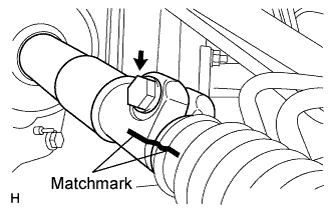 |
Put matchmarks on the No. 2 steering intermediate shaft and steering intermediate shaft.
Remove the bolt and disconnect the No. 2 steering intermediate shaft from the steering intermediate shaft.
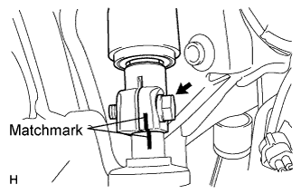 |
Put matchmarks on the No. 2 steering intermediate shaft and the power steering gear.
Remove the bolt and disconnect the No. 2 steering intermediate shaft from the power steering gear.
| 25. REMOVE NO. 2 EXHAUST MANIFOLD HEAT INSULATOR |
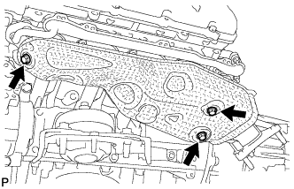 |
Remove the 3 bolts and heat insulator.
| 26. REMOVE EXHAUST MANIFOLD SUB-ASSEMBLY LH |
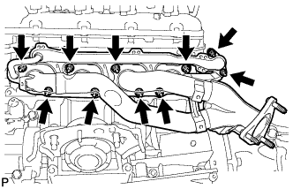 |
Remove the 10 nuts, exhaust manifold and 2 gaskets.
| 27. REMOVE NO. 1 EXHAUST MANIFOLD HEAT INSULATOR |
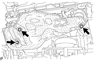 |
Remove the 3 bolts and heat insulator.
| 28. REMOVE EXHAUST MANIFOLD SUB-ASSEMBLY RH |
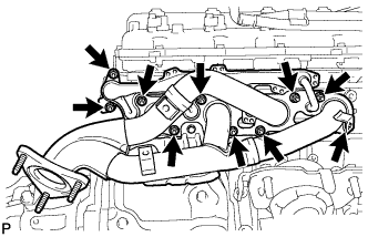 |
Remove the 10 nuts, exhaust manifold and 2 gaskets.