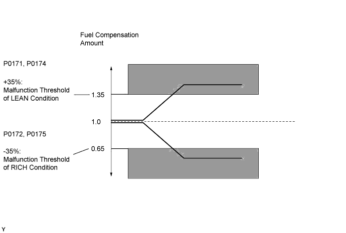
DTC P0171 System Too Lean (Bank 1) |
DTC P0172 System Too Rich (Bank 1) |
DTC P0174 System Too Lean (Bank 2) |
DTC P0175 System Too Rich (Bank 2) |
| DTC Code | DTC Detection Condition | Trouble Area |
| P0171 P0174 | With warm engine and stable air-fuel ratio feedback, fuel trim considerably in error to lean side (2 trip detection logic) |
|
| P0172 P0175 | With warm engine and stable air-fuel ratio feedback, fuel trim considerably in error to rich side (2 trip detection logic) |
|
| Related DTCs | P0171: Fuel trim lean (for Bank 1) P0172: Fuel trim rich (for Bank 1) P0174: Fuel trim lean (for Bank 2) P0175: Fuel trim rich (for Bank 2) |
| Required Sensors/Components (Main) | Fuel system |
| Required Sensors/Components (Related) | A/F sensor, Mass air flow meter, Crankshaft position sensor |
| Frequency of Operation | Continuous |
| Duration | Within 10 seconds |
| MIL Operation | 2 driving cycles |
| Sequence of Operation | None |
| Monitor runs whenever following DTCs not present | P0010, P0020 (VVT Oil control valve) P0011, P0021 (VVT System - Advance) P0012, P0022 (VVT System - Retard) P0013, P0023 (Exhaust VVT Oil control valve) P0014, P0024 (Exhaust VVT System - Advance) P0015, P0025 (Exhaust VVT System - Retard) P0016, P0018 (VVT System - Misalignment) P0017, P0019 (Exhaust VVT System - Misalignment) P0031, P0032, P0051, P0052, P101D, P103D (Air fuel ratio sensor heater) P0102, P0103 (Mass air flow meter) P0115, P0117, P0118 (Engine coolant temperature sensor) P0125 (Insufficient coolant temperature for closed loop fuel control) P0120, P0121, P0122, P0123, P0220, P0222, P0223, P2135 (Throttle position sensor) P0335 (Crankshaft position sensor) P0340, P0342, P0343, P0345, P0347, P0348 (VVT sensor) P0351 - P0358 (Igniter) P0365, P0367, P0368, P0390, P0392, P0393 (Exhaust VVT sensor) P0412, P0415, P0418, P0419, P1613, P1614 (Secondary air injection system control) P1340 (Camshaft position sensor) P2440 - P2447 (Secondary air injection system) P0500 (Vehicle speed sensor) |
| Fuel system status | Closed loop |
| Battery voltage | 11 V or more |
| Either of following conditions 1 or 2 set | - |
| 1. Engine RPM | Below 1100 rpm |
| 2. Intake air amount per revolution | 0.36 g/rev or more |
| Catalyst monitor | Not executed |
| Purge-cut | Executing |
| Either of following conditions 1 or 2 met | - |
| 1. Average of short-term fuel trim and long-term fuel trim | 35% or more (varies with ECT) |
| 2. Average of short-term fuel trim and long-term fuel trim | -35% or less (varies with ECT) |
| Tester Display | Description |
| NORMAL |
|
| ABNORMAL |
|
| INCOMPLETE |
|
| N/A |
|
| 1.CHECK ANY OTHER DTCS OUTPUT (IN ADDITION TO DTC P0171, P0172, P0174 OR P0175) |
Connect the Techstream to the DLC3.
Turn the ignition switch to ON.
Turn the Techstream on.
Enter the following menus: Powertrain / Engine and ECT / Trouble Codes.
Read DTCs.
| Result | Proceed to |
| P0171, P0172, P0174 or P0175 is output | A |
| P0171, P0172, P0174 or P0175 and other DTCs are output | B |
|
| ||||
| A | |
 |
| 2.CHECK PCV HOSE CONNECTIONS |
Check the PCV hose connections .
|
| ||||
| OK | |
|
| 3.CHECK AIR INDUCTION SYSTEM |
Check the air induction system for vacuum leakage .
|
| ||||
| OK | |
|
| 4.PERFORM ACTIVE TEST USING TECHSTREAM (CONTROL THE INJECTION VOLUME FOR A/F SENSOR) |
Connect the Techstream to the DLC3.
Start the engine.
Turn the Techstream on.
Warm up the engine and run the engine at an engine speed of 2500 rpm for approximately 90 seconds.
Enter the following menus: Powertrain / Engine and ECT / Active Test / Control the Injection Volume for A/F Sensor.
Perform the Control the Injection Volume operation with the engine idling.
Monitor the output voltages of the air fuel ratio and heated oxygen sensors (AFS Voltage B1S1 and O2S B1S2 or AFS Voltage B2S1 and O2S B2S2) displayed on the Techstream.
| Techstream Display (Sensor) | Injection Volume | Status | Voltage |
| AFS Voltage B1S1 or AFS Voltage B2S1 (Air fuel ratio) | +12.5% | Rich | Below 3.1 V |
| -12.5% | Lean | Higher than 3.4 V | |
| O2S B1S2 or O2S B2S2 (Heated oxygen) | +12.5% | Rich | Higher than 0.55 V |
| -12.5% | Lean | Below 0.4 V |
| Status of AFS Voltage B1S1 or AFS Voltage B2S1 | Status of O2S B1S2 or O2S B2S2 | Air Fuel Ratio Condition and Air Fuel Ratio Sensor Condition | Suspected Trouble Area | Proceed to |
| Lean/Rich | Lean/Rich | Normal | - | A |
| Lean | Lean | Actual air fuel ratio lean |
| A |
| Rich | Rich | Actual air fuel ratio rich |
| A |
| Lean | Lean/Rich | Air fuel ratio sensor malfunction |
| B |
| Rich | Lean/Rich | Air fuel ratio sensor malfunction |
| B |
|
| ||||
| A | |
|
| 5.READ VALUE USING TECHSTREAM (COOLANT TEMP) |
Connect the Techstream to the DLC3.
Turn the ignition switch to ON.
Turn the Techstream on.
Enter the following menus: Powertrain / Engine and ECT / Data List / All Data / Coolant Temp.
Read the Coolant Temp twice, when the engine is both cold and warmed up.
|
| ||||
| OK | |
|
| 6.READ VALUE USING TECHSTREAM (MAF) |
Connect the Techstream to the DLC3.
Turn the ignition switch to ON.
Turn the Techstream on.
Enter the following menus: Powertrain / Engine and ECT / Data List / All Data / MAF and Coolant Temp.
Allow the engine to idle until the Coolant Temp reaches 75°C (167°F) or more.
Read MAF with the engine speed at 3000 rpm.
|
| ||||
| OK | |
|
| 7.CHECK FUEL PRESSURE |
Check the fuel pressure .
|
| ||||
| OK | |
|
| 8.CHECK FOR EXHAUST GAS LEAK |
Check for exhaust gas leak.
|
| ||||
| OK | |
|
| 9.CHECK FOR SPARKS AND IGNITION |
Perform a spark test .
|
| ||||
| OK | |
|
| 10.INSPECT FUEL INJECTOR (INJECTION AND VOLUME) |
Check the injection volume .
|
| ||||
| OK | |
|
| Go to step 15 |
| 11.INSPECT AIR-FUEL RATIO SENSOR (HEATER RESISTANCE) |
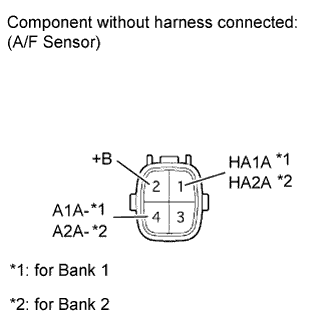 |
Disconnect the D33 or D34 A/F sensor connector.
Measure the resistance according to the value(s) in the table below.
| Tester Connection | Condition | Specified Condition |
| 1 (HA1A) - 2 (+B) | 20°C (68°F) | 1.6 to 3.2 Ω |
| 1 (HA1A) - 4 (A1A-) | Always | 10 kΩ or higher |
| 1 (HA2A) - 2 (+B) | 20°C (68°F) | 1.6 to 3.2 Ω |
| 1 (HA2A) - 4 (A2A-) | Always | 10 kΩ or higher |
|
| ||||
| OK | |
|
| 12.CHECK TERMINAL VOLTAGE (+B OF AIR FUEL RATIO SENSOR) |
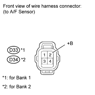 |
Disconnect the D33 or D34 A/F sensor connector.
Turn the ignition switch to ON.
Measure the voltage according to the value(s) in the table below.
| Tester Connection | Switch Condition | Specified Condition |
| D33-2 (+B) - Body ground | Ignition switch ON | 11 to 14 V |
| D34-2 (+B) - Body ground | Ignition switch ON | 11 to 14 V |
| Result | Proceed to |
| NG | A |
| OK | B |
|
| ||||
| OK | |
|
| 13.CHECK HARNESS AND CONNECTOR (AIR FUEL RATIO SENSOR - ECM) |
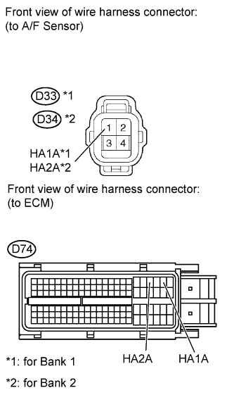 |
Disconnect the D33 or D34 A/F sensor connector.
Disconnect the D74 ECM connector.
Measure the resistance according to the value(s) in the table below.
| Tester Connection | Condition | Specified Condition |
| D33-1 (HA1A) - D74-22 (HA1A) | Always | Below 1 Ω |
| D34-1 (HA2A) - D74-20 (HA2A) | Always | Below 1 Ω |
| D33-1 (HA1A) or D74-22 (HA1A) - Body ground | Always | 10 kΩ or higher |
| D34-1 (HA2A) or D74-20 (HA2A) - Body ground | Always | 10 kΩ or higher |
|
| ||||
| OK | |
|
| 14.REPLACE AIR FUEL RATIO SENSOR |
Replace the air fuel ratio sensor (Click here).
| NEXT | |
|
| 15.CHECK WHETHER DTC OUTPUT RECURS (DTC P0171, P0172, P0174 OR P0175) |
Connect the Techstream to the DLC3.
Turn the ignition switch to ON.
Turn the Techstream on.
Clear DTCs (Click here).
Turn the ignition switch off and wait for at least 30 seconds.
Turn the ignition switch to ON and turn the Techstream on.
Start the engine and warm it up.
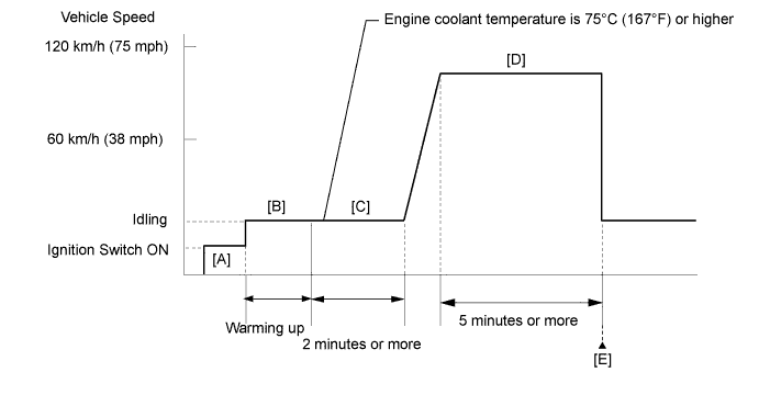
Drive the vehicle in accordance with the driving pattern described in Confirmation Driving Pattern.
Enter the following menus: Powertrain / Engine and ECT / Trouble Codes.
Read DTCs.
| Result | Proceed to |
| DTC P0171, P0172, P0174 or P0175 is output | A |
| DTC is not output | B |
|
| ||||
| A | |
|
| 16.CHECK HARNESS AND CONNECTOR |
Check the connection and terminal contact pressure of connectors and wire harnesses between the mass air flow meter and ECM (Click here).
| NEXT | |
|
| 17.CHECK WHETHER DTC OUTPUT RECURS (DTC P0171, P0172, P0174 OR P0175) |
Connect the Techstream to the DLC3.
Turn the ignition switch to ON.
Turn the Techstream on.
Clear the DTCs (Click here).
Turn the ignition switch off and wait for at least 30 seconds.
Turn the ignition switch to ON and turn the Techstream on.
Start the engine and warm it up.
Drive the vehicle in accordance with the driving pattern described in Confirmation Driving Pattern.
Enter the following menus: Powertrain / Engine and ECT / Trouble Codes.
Read DTCs.
| Result | Proceed to |
| DTC P0171, P0172, P0174 or P0175 is output | A |
| DTC is not output | B |
|
| ||||
| A | |
|
| 18.CHECK HARNESS AND CONNECTOR (A/F SENSOR - ECM) |
Disconnect the D7 MAF meter connector.
Disconnect the D74 ECM connector.
Measure the resistance according to the value(s) in the table below.
| Tester Connection | Condition | Specified Condition |
| D7-3 (VG) - D74-74 (VG) | Always | Below 1 Ω |
| D7-2 (E2G) - D74-75 (E2G) | Always | Below 1 Ω |
| D7-3 (VG) or D74-74 (VG) - Body ground | Always | 10 kΩ or higher |
|
| ||||
| OK | |
|
| 19.REPLACE MASS AIR FLOW METER |
Replace the mass air flow meter (Click here).
| NEXT | |
|
| 20.CONFIRM WHETHER MALFUNCTION HAS BEEN SUCCESSFULLY REPAIRED |
Connect the Techstream to the DLC3.
Turn the ignition switch to ON.
Turn the Techstream on.
Clear the DTCs (Click here).
Turn the ignition switch off and wait for at least 30 seconds.
Turn the ignition switch to ON and turn the Techstream on.
Start the engine and warm it up.
Drive the vehicle in accordance with the driving pattern described in Confirmation Driving Pattern.
Enter the following menus: Powertrain / Engine and ECT / Trouble Codes.
Read DTCs.
| Result Result | Proceed to |
| DTC is not output | A |
| DTC P0171, P0172, P0174 or P0175 is output | B |
|
| ||||
| A | ||
 | ||
| ||
| 21.CHECK HARNESS AND CONNECTOR (AIR FUEL RATIO SENSOR - NO. 1 INTEGRATION RELAY) |
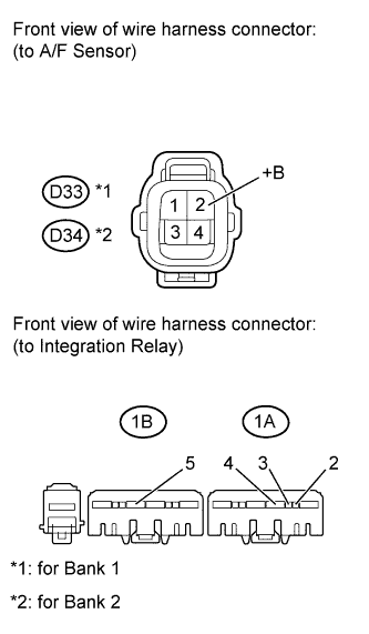 |
Disconnect the D33 or D34 A/F sensor connector.
Remove the integration relay from the engine room relay block .
Measure the resistance according to the value(s) in the table below.
| Tester Connection | Condition | Specified Condition |
| D33-2 (+B) - 1A-4 | Always | Below 1 Ω |
| D34-2 (+B) - 1A-4 | Always | Below 1 Ω |
| 1A-2 - 1B-5 | Always | Below 1 Ω |
| 1A-3 - Body ground | Always | Below 1 Ω |
| D33-2 (+B) or 1A-4 - Body ground | Always | 10 kΩ or higher |
| D34-2 (+B) or 1A-4 - Body ground | Always | 10 kΩ or higher |
| 1A-2 or 1B-5 - Body ground | Always | 10 kΩ or higher |
|
| ||||
| OK | |
|
| 22.INSPECT INTEGRATION RELAY (A/F) |
Inspect the integration relay (A/F) .
|
| ||||
| OK | ||
| ||
| ||

